Introduction
In this installation guide we have provided step by step instructions to remove the OEM rear brakes and install the 27WON Performance Big Brake Kit.
Advisory:
- Working under the vehicle requires a safe and sturdy location for the vehicle to sit on jackstands.
- The brake rotors can be hot after recent vehicle operation. Allow the vehicle to cool or use a fan to cool the brake rotors before working on the vehicle.
Tools
- Hydraulic Jack
- Jack Stand × 2
- 3/8" Ratchet
- 3/8" Long Extension
- 10mm Socket
- 12mm Socket
- 14mm Socket
- 10mm Line Wrench
- 7mm Wrench
- 17mm Box-End Wrench
- 19mm Box-End Wrench
- 14mm Wrench
- 8mm Allen Key Socket
- Crescent Wrench
- 3/8" Breaker Bar
- 1/2" Torque Wrench
- Lug Nut Socket
- Phillips Screwdriver - #3
- Phillips Impact Driver
- Vice Grip Pliers
- Pry Bar
- Tin Snips
- Cut Off Wheel (optional)
- Hammer
- Brake Fluid-DOT 3
- Locktite, Blue
- Brake Clean Spray
- PB Blaster
- Flat Black Spray Paint
- Catch Tray
- Shop Towels/Rags
- 90 Degree Pick Tool
- Flat Head Screwdriver - Large
- 5mm Allen Wrench
-
-
First and foremost; THANK YOU for becoming a part of the 27WON Family. We hope to REDEFINE your experience of the aftermarket with the highest level Parts, Customer Service, Packaging, & Support
-
Located at the end of these installation instructions is a How-To Guide for Brake Pad Replacement
-
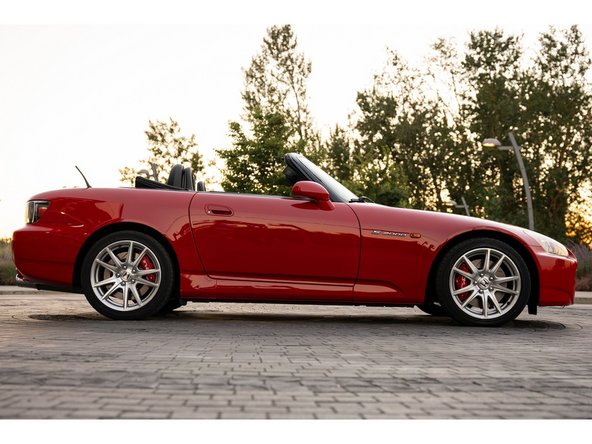
These instructions were written on a 2005 Honda S2000 with slightly larger rear rotors. Install is similar for your application
-
Trimming of brake dust shields is required to accommodate the caliper brake bracket. See Step 14
-
Provided brake pads are for spirited street use. For track use, different pads are required. See step 45 for recommendations
-
-
-
OEM wheels will require the use of a wheel spacers for proper clearance and operation
-
Some aftermarket wheels will require the use of a wheel spacer for proper clearance and operation
-
Use this Wheel Fitment Guide link to check the BBK clearance for your wheels: https://store.27won.com/_27Won/27Won-1-P...
-
-
-
These instructions reference the separate sides of the vehicle as "Left Hand" & "Right Hand". Left Hand & Right Hand is always defined from the driver seat viewpoint
-
Brake fluid is corrosive to paint. Do not let brake fluid sit on painted surfaces for extended periods of time
-
-
-
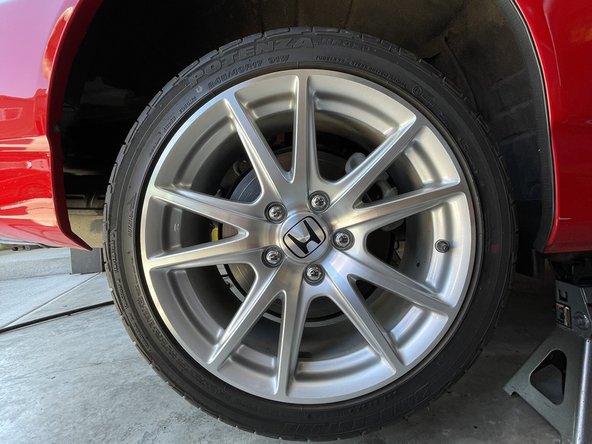
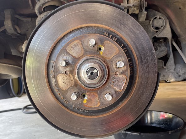
Raise the vehicle and support with jack stands in the OE recommended locations and remove the rear wheels/tires
-
The following instructions show the right hand side complete removal of OE components and installation of 27WON BBK. The left hand side is completed with the same steps
-
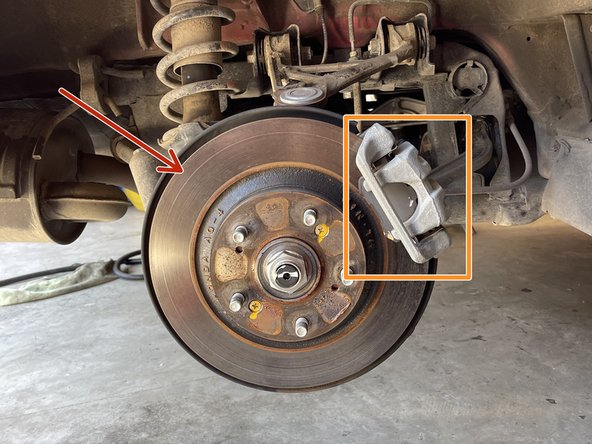
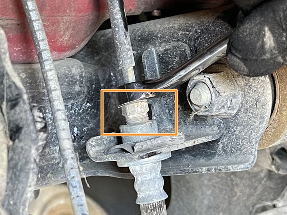
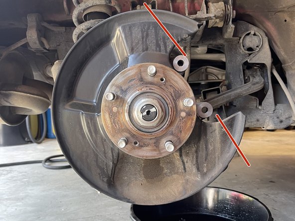
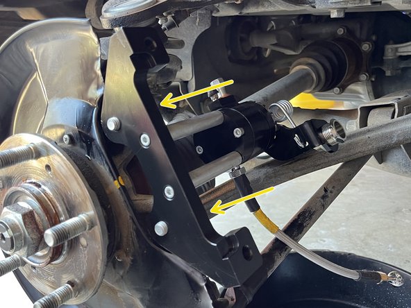
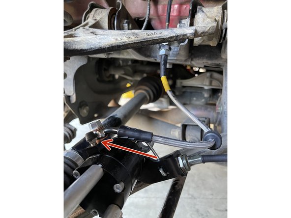
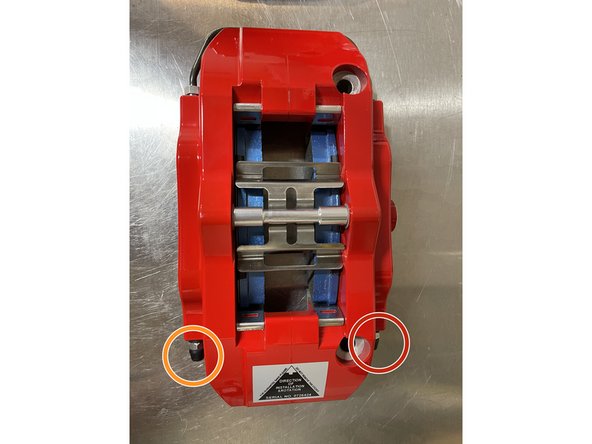
Brake Rotor, see red arrow
-
Brake Caliper, see orange box
-
Once the rear of the car is secure on jack stands, disengage your parking brake
-
-
-
Place a drain pan under the caliper to catch brake fluid from brake hose
-
Using a 12mm socket with a 3/8" ratchet, remove the banjo bolt holding the OEM brake hose to the caliper so it can drain into the drain pan while disassembling
-
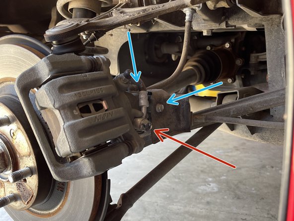
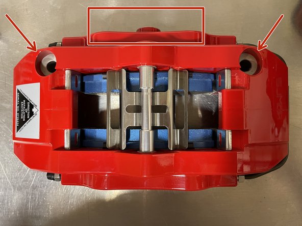
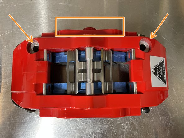
Using a 10 mm socket, remove the (2) 10mm bolts holding the metal cover
-
Remove (2) 10mm bolts holding the brake hose bracket
-
-
-
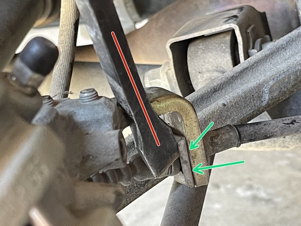
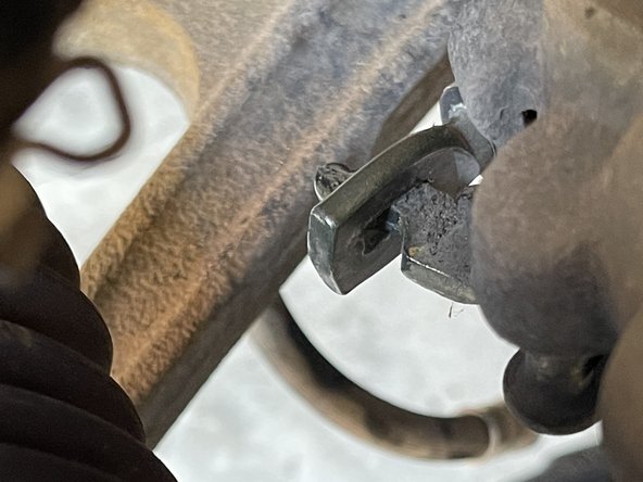
Using a small pry bar, remove the metal clip securing the parking brake cable to the metal bracket
-
Clip
-
-
-
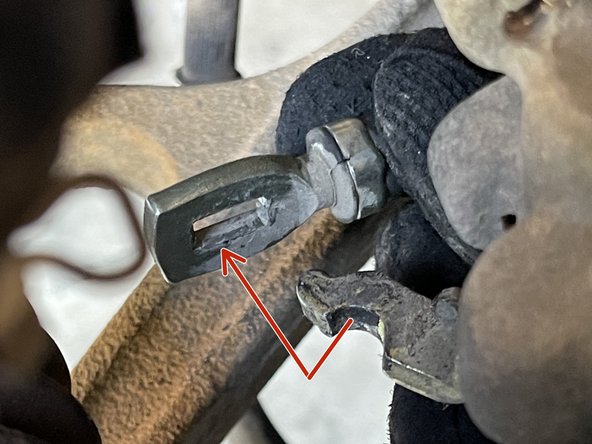
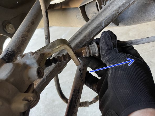
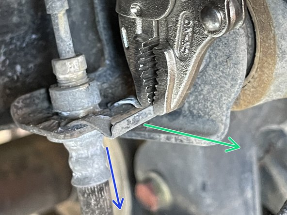
Pull the parking brake cable forward and away as shown
-
Remove the parking brake cable from the metal bracket
-
-
-
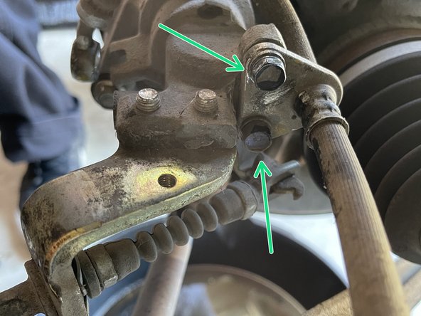
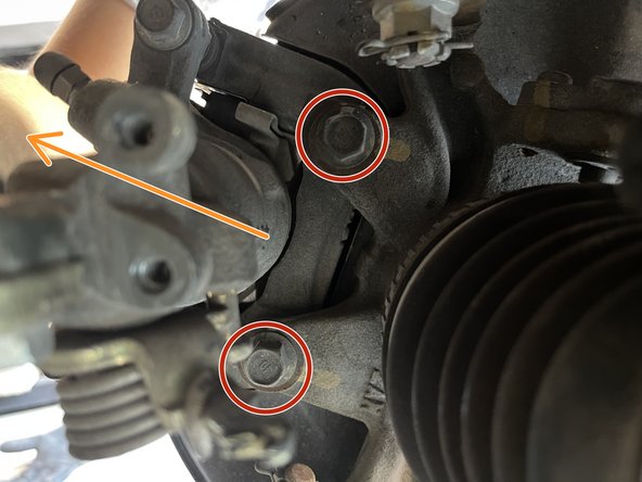
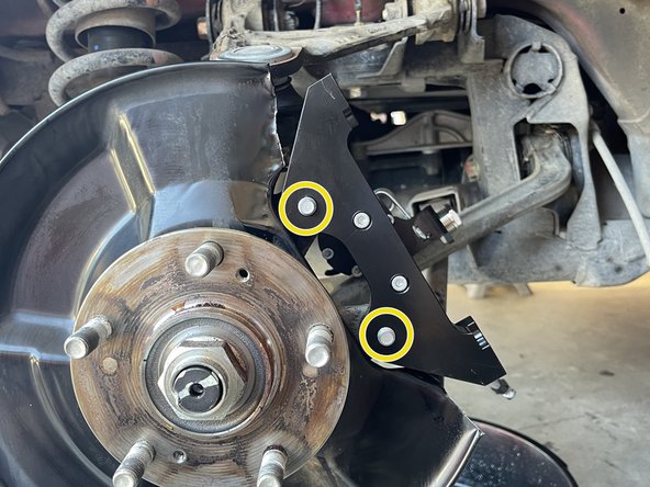
Using 14mm socket and 3/8" breaker bar, remove the (2) 14mm bolts holding the caliper bracket to the knuckle
-
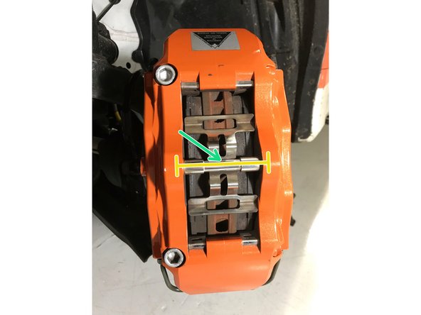
With the bolts removed, slide the brake caliper off the rotor in the direction of the orange arrow
-
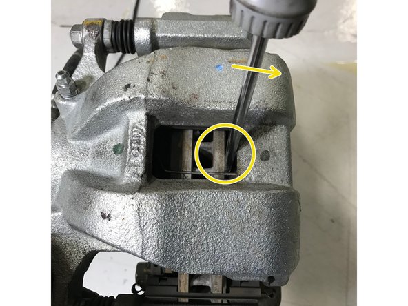
If the rotor is heavily worn, you may need to spread the brake pads apart to gain clearance
-
Use a large flat head screwdriver to pry between the brake pad and the rotor as shown
-
-
-
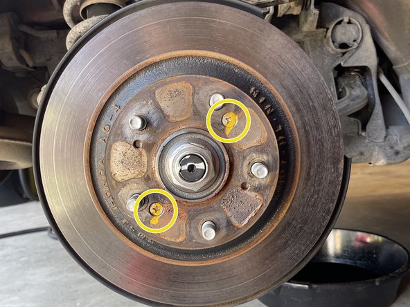
Using an impact driver and hammer, remove the (2) Phillips screws holding on the rotor
-
If there is a lot of corrosion around your rotor, spray with a bolt penetrant like PB blaster for easier removal
-
-
-
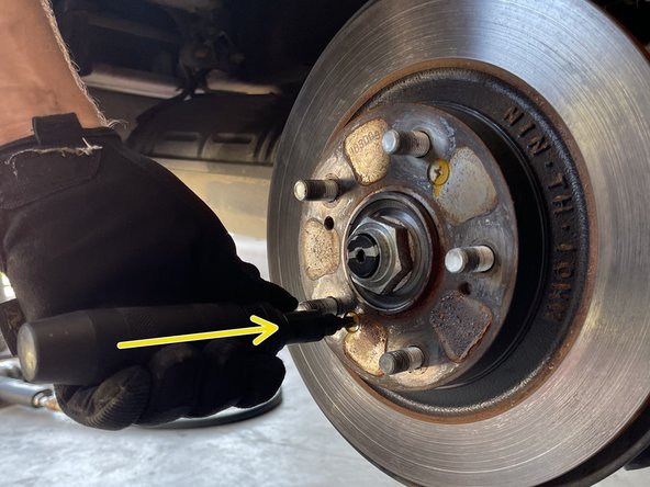
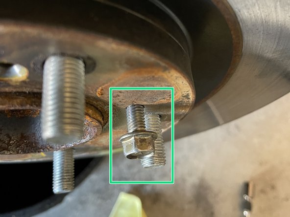
Remove the brake rotor from the hub
-
If the rotor is seized, use a M6x1.00 bolt removed from Step 5 to thread into the threaded holes of the rotor and it will be lifted from the hub
-
Be careful not to damage any hardware as it will be used again
-
-
-
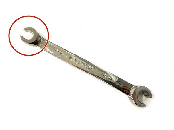
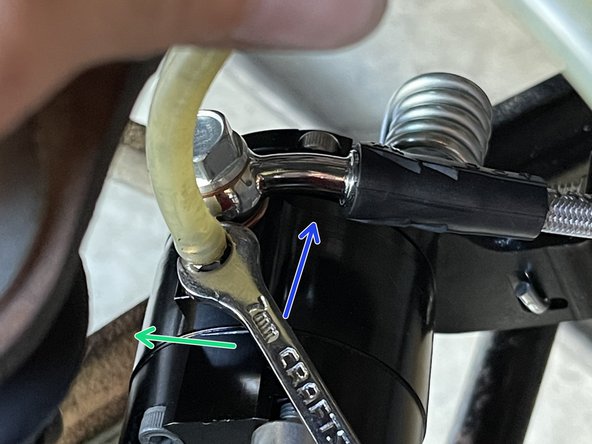
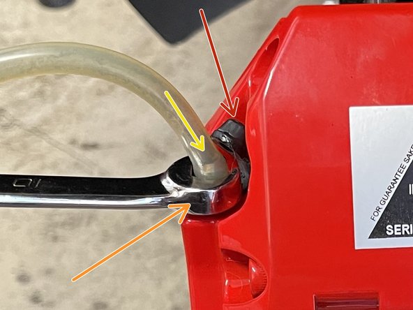
It is critical to use a Line Wrench to loosen the brakeline connection. Using the open end of a standard wrench may round the nut on the OE brake line
-
Use a 10mm line wrench to loosen the threaded brake line connection (shown with orange box)
-
-
-
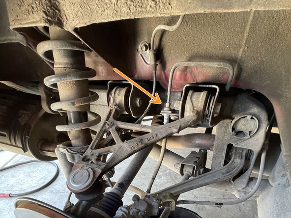
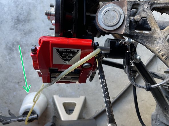
Using a small prybar or vice grips, remove the brake hardline clip
-
It’s very possible this clip could be stuck. We recommend applying PB blaster around it if needed
-
Once the clip is removed, you can pull out the OEM brake hose from the car
-
-
-
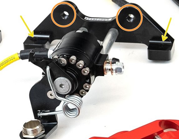
Caliper Bracket
-
Mounting holes to vehicle
-
Mounting holes to BBK Caliper
-
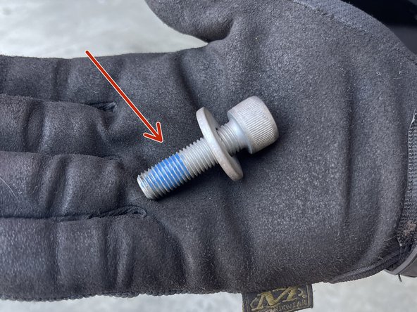
Caliper Bracket Retaining Bolt
-
-
-
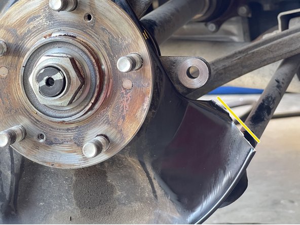
Trimming is required to accommodate the size of the caliper/parking-brake bracket
-
Using tin snips or a cut off wheel, trim the brake dust cover as shown
-
We recommend applying some paint over the raw metal to prevent corrosion
-
-
-
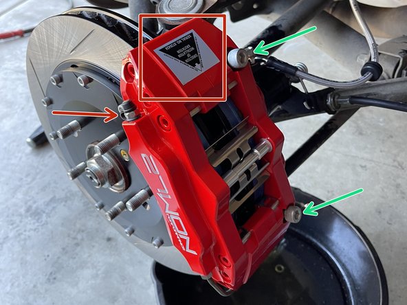
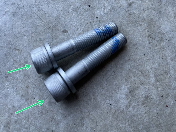
It's recommended applying blue Loctite onto the caliper bracket retaining bolt as shown
-
Using the shorter provided (2) 10mm Allen bolts, install the caliper/parking brake assembly to the knuckle
-
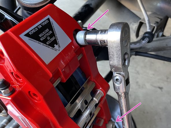
Hand thread the caliper bracket retaining bolt as shown
-
Using the 10mm hex bit socket and torque wrench, torque to 64-71 ft-lbs
-
-
-
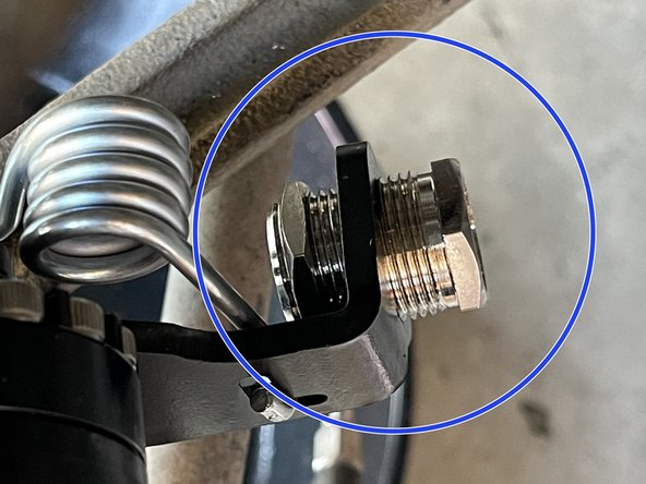
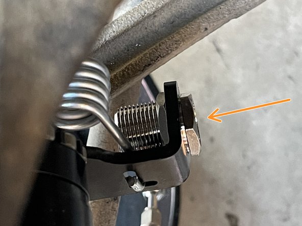
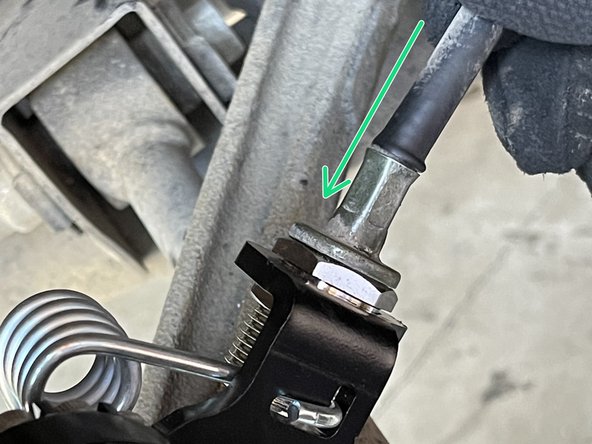
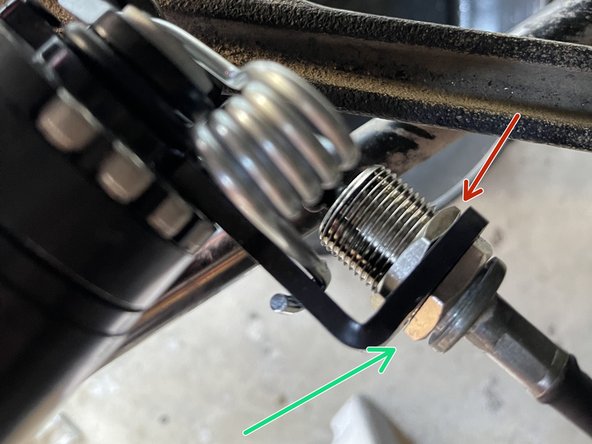
The parking brake assembly has an adjuster screw to adjust brake cable tension
-
Using a crescent wrench, adjust this all the way in as shown to help ease your install
-
You will adjust this later
-
-
-
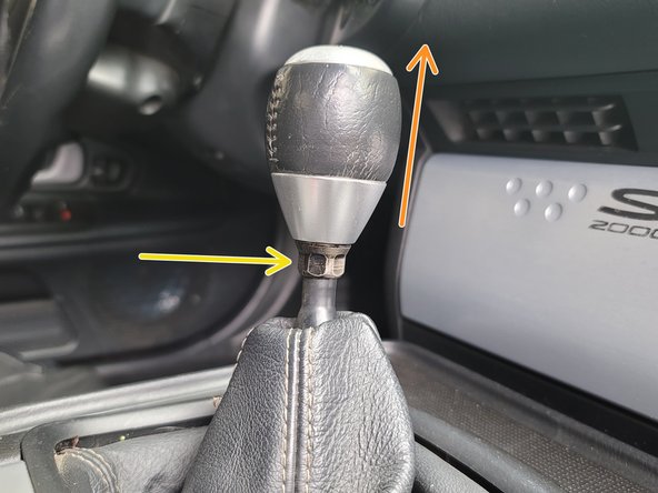
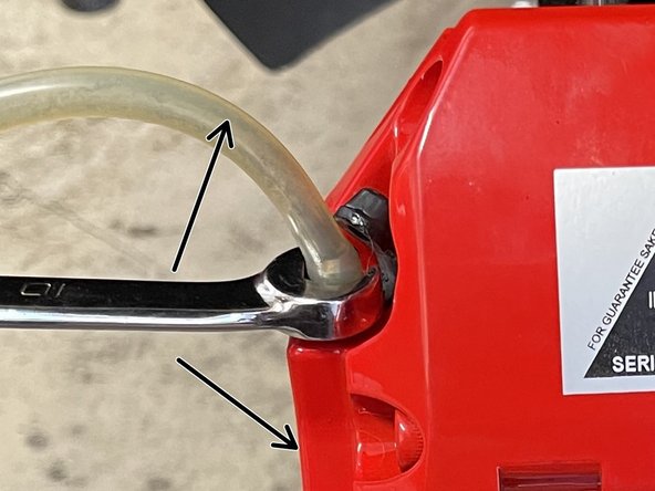
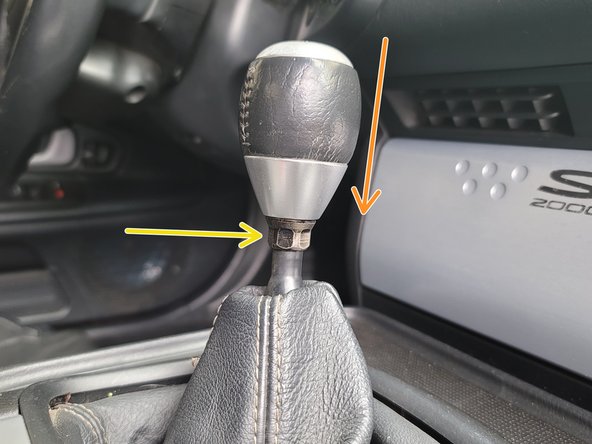
Using a 14mm wrench, loosen the 14mm locking nut on the shift knob
-
Un-thread the shift knob from the shifter and set aside
-
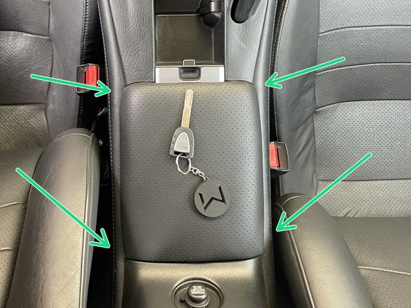
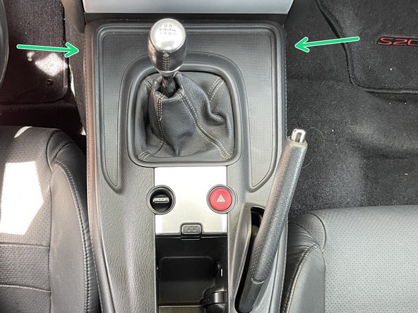
Start in the back corner and work your way around the center console and using your hands, unclip the retainer clips from the transmission tunnel by pulling up with mild force
-
-
-
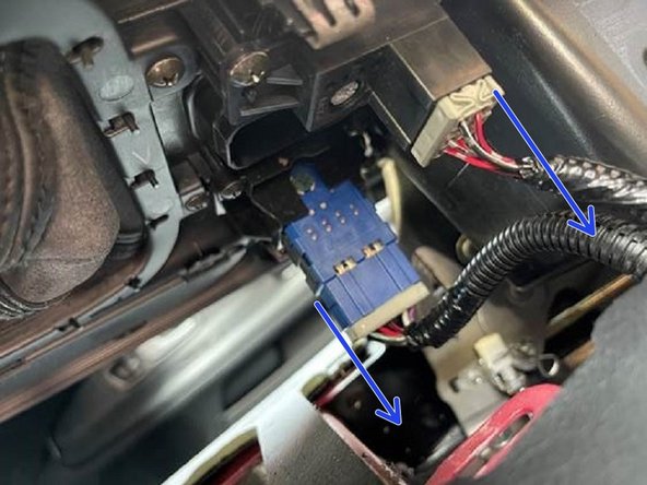
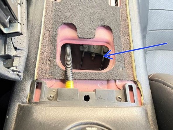
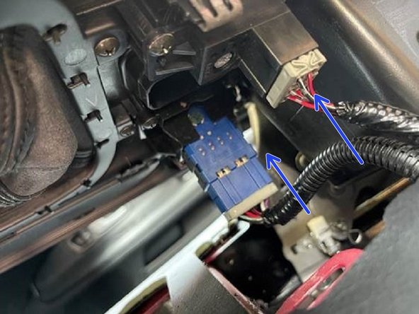
Unplug the (2) pigtail clips from the center console cover
-
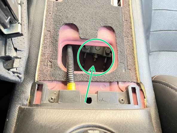
Remove the center console cover by lifting up and over the shifter. Set the cover aside
-
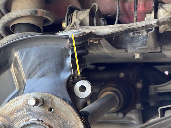
Notice: the second image shows where you will be adjusting your parking brake later
-
-
-
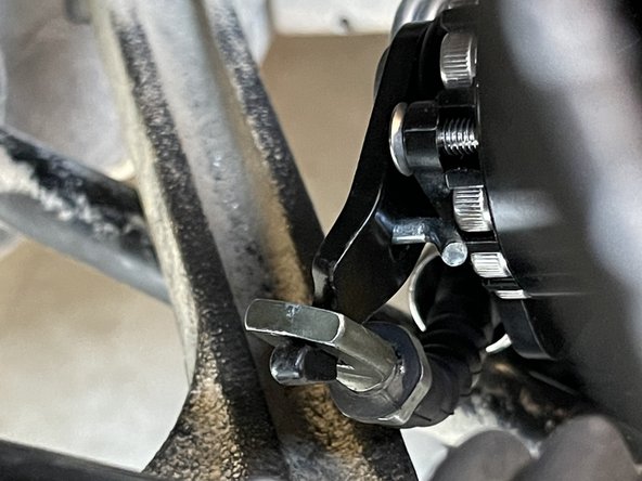
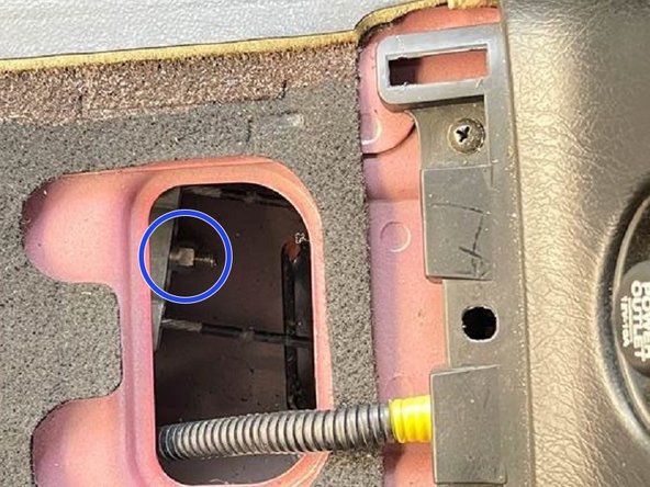
Make sure the adjustment screw is fully threaded in as shown in Step 16
-
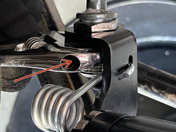
Guide the parking brake cable through the adjustment screw
-
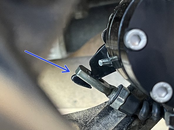
-
-
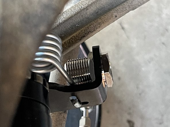
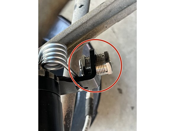
Hook the cable around the parking brake mechanism as shown
-
If the cable does not have enough slack to be hooked on, you will have to loosen the parking brake cable nut under the center console
-
-
-
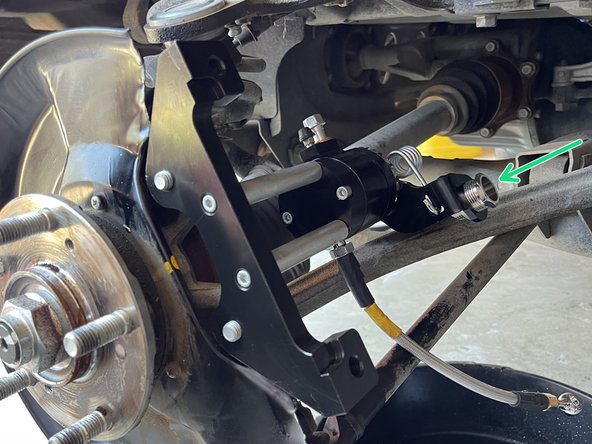
Using the crescent wrench, unthread the adjustment screw to apply mild tension to the cable
-
You may find the adjustment screw threaded out about halfway to be the ideal spot, this spot would be mild tension where a small push by your hand causes the line to flex
-
Using the crescent wrench, tighten the locking nut against the bracket
-
The final parking brake adjustment will be done later
-
-
-
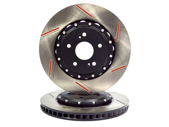
The 27WON BBK has directional brake rotors. It is therefore critical that the correct rotor is installed on the correct side of the vehicle
-
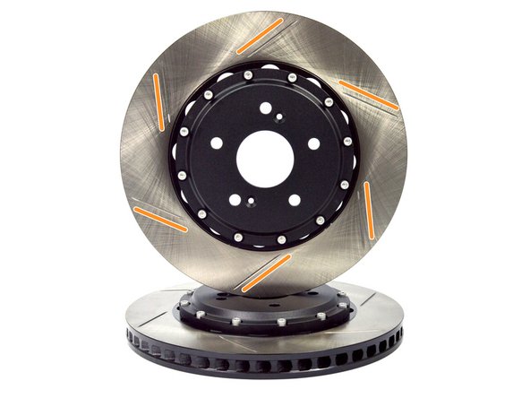
The direction of the angled slots allows you to identify if the rotor is LH or RH
-
Left Hand Rotor (LH) - This rotor will go on the Left Hand side of the vehicle
-
For North American cars this is the driver side
-
Right Hand Rotor (RH) - This rotor will go on the Right Hand side of the vehicle
-
Rotors come with machine oil on them to resist corrosion - clean both rotors with brake cleaner spray and clean rag
-
-
-
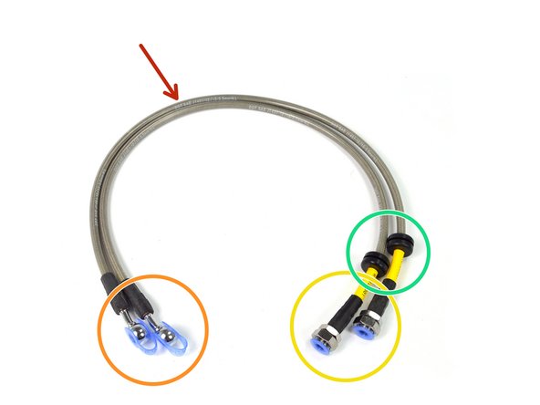
Locate the provided stainless steel braided brake hoses
-
Caliper side of brake hose w/blue dust cover
-
Chassis side of brake hose w/blue dust cover
-
Rubber Strut Mount Isolators
-
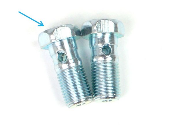
Locate the provided Banjo Bolts
-
Locate the provided 10mm Crush Washers
-
-
-
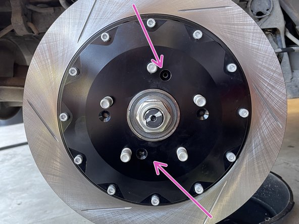
The rotor needs to be fitted so that the two screw holes are aligned
-
Use the (2) OEM Philips retaining screws secure the rotor as shown
-
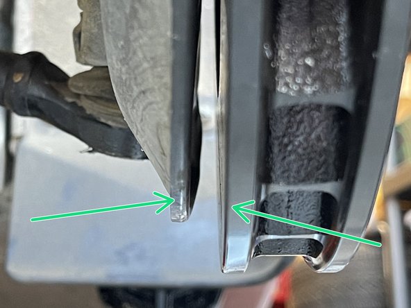
Use a pry bar to deflect the shield to make sure the dust shield doesn't make contact on the rotor. Be sure and have a minimum of 2-3mm from back of rotor to dust shield
-
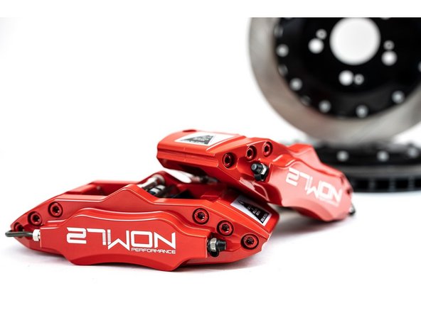
-
-
27WON BBK has directional brake calipers - therefore it is critical that the correct caliper is installed on the correct side of the vehicle
-
Left Hand Caliper - This caliper will go on the Left Hand side of the vehicle
-
For North American cars this is the driver side
-
Right Hand Caliper - This caliper will go on the Right Hand side of the vehicle
-
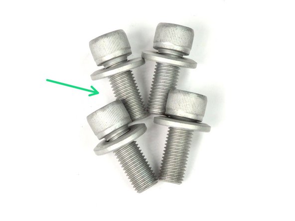
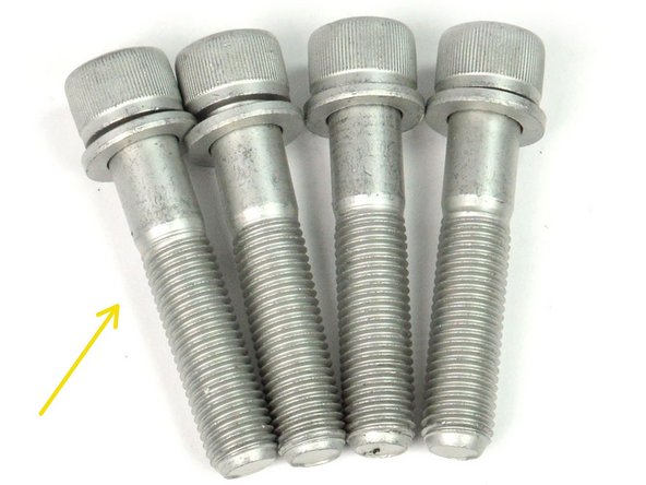
Long Socket Cap Bolts
-
Included with the hardware is a pack of very thin washers. These are used as spacers for the rare case that the position of the caliper needs to be adjusted
-
-
-
Note the orientation of the left caliper versus the right caliper by the sticker that shows the direction of rotation, and make sure the brake bleeder is pointing up
-
Apply blue Loctite on (2) M8 long socket cap bolts
-
Install the caliper on to the caliper bracket as shown
-
Install the 8mm (2) long socket cap bolts
-
Using the 8mm hex bit socket and torque wrench, torque to 64-71 ft-lbs
-
-
-
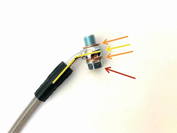
Banjo Bolt
-
Crush Washer
-
Brake hose - Notice the angle of the brake hose, verify the head of the banjo bolt is on this side as shown
-
Installation of brake hose to caliper on opposite angle may cause a crush washer leak
-
Crush Washer
-
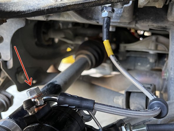
Using one of the provided 10mm banjo bolts and crush washers, install short included brake hose from the parking brake to caliper
-
Make sure the crush washers are installed as shown
-
Using a 12mm socket and torque wrench - torque to 8-12 ft-lbs
-
-
-
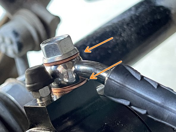
Attach the brake hose to the parking brake assembly with (2) crush washers as shown
-
Route the hose as shown
-
Using a 12mm socket and torque wrench - torque to 8-12 ft-lbs
-
-
-
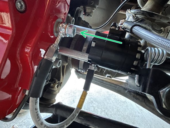
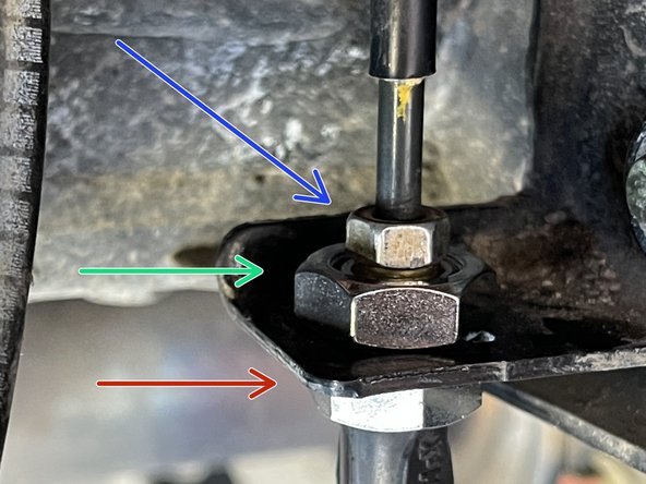
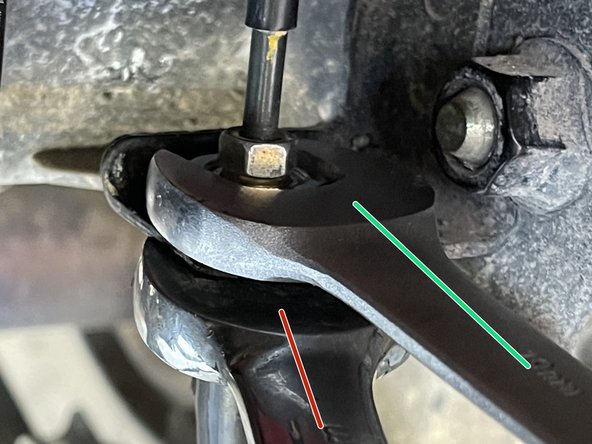
Install the 27WON brake hose into the bracket
-
The 19mm nut on top will spin off, then you insert the line into the bracket, and then reinstall the 19mm nut
-
Use a 17mm wrench to secure the bottom nut
-
Use 19mm wrench on the top nut, tighten the line into place
-
Using a 10mm line wrench, tighten the OEM hardline into the 27WON brake hose
-
-
-
This completes the BBK installation for the right hand side of the vehicle. The left hand installation process is the same
-
Complete the left hand installation process starting on Step 4
-
Located at the end of these installation instructions is a How-To Guide for Brake Pad Changes
-
-
-
Do not proceed until brake kit is installed on both sides
-
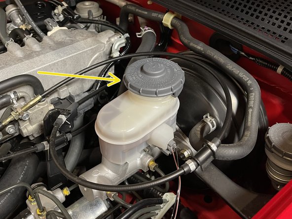
Make sure you top off your fluid in the reservoir using Honda recommended DOT 3 brake fluid
-
Ensure throughout this process you monitor the fluid level and don’t let the reservoir become completely empty
-
On the rear kit you must start the bleeding at the parking brake module. This will make sure you get all the air bubbles out of the parking brake assembly prior to bleeding the calipers themselves
-
-
-
Order of brake bleeding will be at the following spots
-
Right hand side parking brake assembly
-
Left hand side parking brake assembly
-
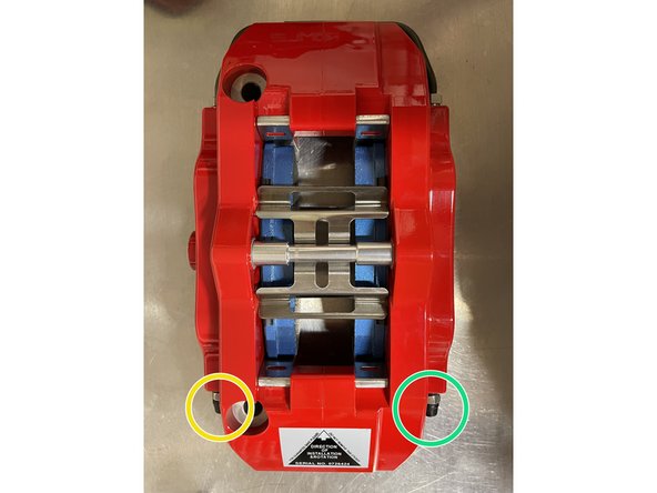
Right hand side caliper outer bleeder screw
-
Right hand side caliper inner bleeder screw
-
Left hand side caliper outer bleeder screw
-
Left hand side caliper inner bleeder screw
-
-
-
Both Left Hand and Right Hand BBK Systems must be installed completely before proceeding to the Brake Bleeding Procedure
-
Clean all brakeline connections at chassis and caliper with brake clean spray and clean rag
-
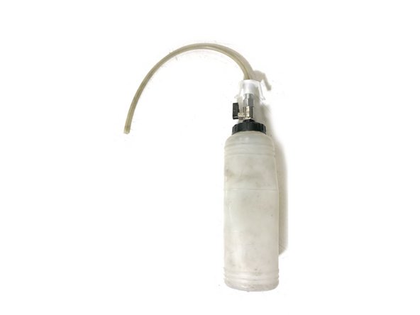
Tools - You will need a fresh container of Dot 3 Brake Fluid, bleeder bottle and hose as shown (the hose should fit tight on the bleeder screw), 10mm box-end wrench, and a friend to help with the process
-
For best results, always start with the bleed screw located the furthest away from the master cylinder and work your way closer. There are two bleed screws for each caliper. Follow the order below. This is completed after the parking brake modules are bleed
-
First Bleed Screw - RH Outside
-
Second Bleed Screw - RH Inside
-
Third Bleed Screw - LH Outside
-
Last Bleed Screw - LH Inside
-
-
-
Starting at the wheel furthest from the Master Cylinder, attach a drain tube to the bleeder on the Parking Brake Assembly. Have someone in the driver's seat to pump the brakes. Pump 3 times and hold
-
While they are holding pressure on the pedal, you will loosen the bleeder. To do this, use a 7mm wrench and rotate left
-
Once the pedal hits the floor, have them hold it there until you tighten the bleeder. Once tight they can release
-
The process of opening this bleeder screw will force fluid from the chamber into the brake system, and force air out. Repeat this process until you see non aerated fluid coming out of the drain tube
-
-
-
Remove the cap from the bleed screw as shown
-
Place the box end of the 10mm wrench over the bleed screw hex as shown
-
Put one end of the hose on the bleed screw as shown
-
Hang bottle from wheel studs as shown or set on ground
-
Have yourself or your friend setup in the driver's seat so that they can press the brake pedal firmly
-
Have the other person setup at the brake caliper so they can open/close the bleed screw
-
To open/close the bleed screw - you only need to turn the wrench ~1/4 turn
-
-
-
Have the person in the driver's seat press the brake pedal 3-5 times until there is sufficient pedal pressure. Then, have them hold the brake pedal firmly as the bleed screw is loosened. The pedal will go to the floor while fluid and air will enter the bottle. Make sure your friend holds the pedal down as you retighten the bleed screw
-
The brake pedal will go to the floor while fluid and air will be pushed through the open bleed screw
-
Continue holding the brake pedal down until the bleed screw is re-tightened/closed
-
Repeat the above procedure around 3-5 times per bleed screw, or until your are confident there is no air in the system Check that your brake fluid level is at “full” after each bleed screw
-
After each bleed screw is completed, check that your brake fluid level is at “full”. Refill as needed
-
Now go back to step 33 and repeat for other side
-
Once brake bleeding is complete, inspect all brake line connections at chassis and caliper and parking brake assembly to verify there are no leaks
-
-
-
Adjustment of the parking brake is necessary for proper operation. This must be done before installation is completed
-
Before proceeding, reinstall wheels and tires with the car still supported by jack stands, lug nuts need only be snug for this step around 30 ft-lbs
-
You will be spinning the rear wheels by hand to check parking brake operation later
-
Wheels and tires will be torqued after this process is completed and car back on the ground safely
-
-
-
Per the factory service manual, the parking brake must be fully engaged between 9-13 clicks of the parking brake handle. It should very lightly drag on 1 click and have no drag at all when the parking brake is fully lowered
-
Using a 10mm socket, adjust the screw as needed to comply with the parking brake adjustment guideline
-
Make sure you cannot spin the wheel and tire by hand at 9-13 clicks while jack stands still support the rear end of car. If you can then engagement is not set properly
-
If further adjustment is required outside of the adjusting nut under the transmission tunnel then the tension of the cable at the parking brake module can be adjusted as well to comply with the above guidelines.
-
Reference step 21 for how to adjust the screw
-
-
-
Plug the (2) pigtail clips on to the center console cover
-
Reclip the center console cover in their respective clip locations
-
Shift knob shown installed. See next step
-
-
-
Thread the shift knob back in the shifter
-
Using a 14mm wrench, tighten the locking nut to secure the shift knob
-
-
-
Using a jack, raise the vehicle and remove the supporting jack stands. Safely, lower the vehicle to the ground
-
Torque the lug nuts on your wheels to the manufacturer recommended specifications
-
-
-
If the brakes are properly bleed the brake pedal should have distinct "feel" to it
-
Brake pedal should have minimal down travel before pressure/force is felt
-
Brake pedal should feel firm after a small amount of down travel - it should not feel "spongy" or loose pressure over a quick amount of time
-
If your brake pedal does not correlate with the above, then go through the brake bleeding procedure again
-
-
-
Before parking your car on a hill, verify your parking brake is functioning properly
-
We recommend verifying Parking Brake function before proceeding to brake pad bedding procedure. Safety first!
-
Find a safe testing location that has a slightly inclined road. Some driveways are perfect for this. It is highly recommended this be away from any obstacles and people
-
Park your car on the incline. Put it into neutral while your foot is depressing the brake pedal to keep the car from moving
-
Fully engage your parking brake and slowly release your foot from the brake pedal. The car should not move
-
If your parking brake DOES NOT hold your car, adjust brake line tension as previously indicated in this guide
-
-
-
Brake pad bedding is an essential process to the life and durability of the brake pads and rotors - for optimal BBK performance please follow the steps below
-
Proper pad bedding slowly heats and cools the rotors & pads - do not hard brake during initial driving until after complete bedding procedure is complete
-
Find an open road and accelerate to 30mph - Brake evenly and smoothly at ~50% effort until the vehicle is almost stopped, then accelerate to 30mph again
-
Repeat above step 8-10 times
-
Find an open road and accelerate to 50mph - Brake evenly and smoothly at ~80% effort until the vehicle is almost stopped, then accelerate to 50mph again
-
Repeat above step 2-3 times
-
Allow ~15min for brakes to cool - You can now use the brakes for normal driving
-
-
-
All braking systems are a compromise of Performance, Dust, and Noise. These factors are all highly dependent on the brake pad material used
-
The 27WON BBK arrives to your door with a brake pad material we found to be a good compromise of the above three factors. The pad material is consider a "street sport" setup that will provide a low amount of dust, nearly zero noise (some noise if very cold), and good performance for most street driven applications
-
The 27WON BBK is designed around a very common pad size and shape. If desired you may seek out a brake pad compound that better suits your driving style and application
-
Brake Pad Options by Manufacturer - There are many more options available than shown
-
Hawk – HB107
-
FPC – PF7740
-
AP Racing – CP2340D40 & CP2340D43
-
Alcon – 4463
-
-
-
This completes the installation & setup of your 27WON Performance Rear Big Brake Kit
-
We hope you were impressed with your 27WON experience and love your new BBK for years to come. Email us at sales@27won.com or call us at 571-271-0271 with any questions or concerns
-
Please Leave a review here: https://store.27won.com/2000-2009-honda-...
-
Share your experience using #27WON on Instagram and Facebook
-
Proceed to the next step for the How-To Guide for Brake Pad Replacement
-
-
-
These instructions were written on a Honda Civic. Steps for the 27WON BBK on a S2K are the same
-
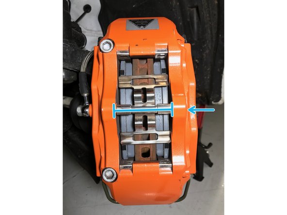
Using a 5mm Allen wrench, remove the caliper bridge bolt
-
While loosening the bolt, push on the bridge spacer towards the rotor then remove the bolt
-
Remove bridge spacer and spring clip
-
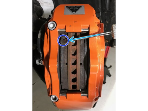
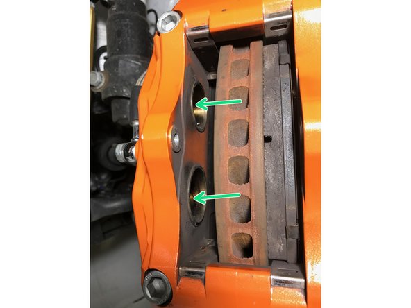
Using a flathead screwdriver, push the brake pad away from the rotor as shown to provide clearance
-
Typically the brake pad backer plate has a small edge that can be pushed against
-
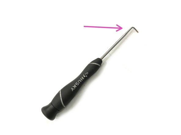
Locate the 90 degree pick tool for the next step
-
-
-
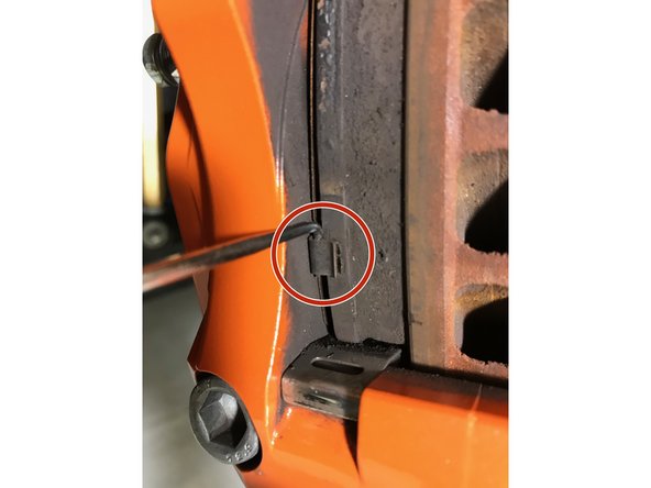
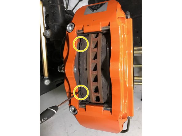
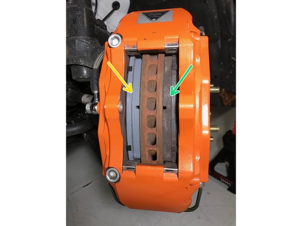
Using a 90deg pick tool, hook the pick on the backer plate of the brake pad then remove brake pad
-
Pull the top and bottom of the brake pad in even increments until the pad can be fully removed
-
With the brake pad removed you can now access the caliper pistons directly - you will need to fully press the pistons into the caliper to provide clearance for new brake pads
-
Sometimes while pressing one piston in, another piston will push out. If necessary, hold the other pistons in place while pressing a piston into the caliper
-
-
-
Install the new brake pad into the caliper as shown
-
Verify the brake pad material surface is towards the rotor face and the backer plate is towards the pistons
-
Repeat Step 47 & 48 for the remaining used brake pad
-
Re-install the brake pad spring clip and the caliper bridge spacer - hand thread the caliper bridge bolt and torque to 8-10 ft-lbs
-
Complete the Brake Pad Bedding Procedure in Step 44
-