Introduction
In this installation guide we have provided step by step instructions to remove the OEM downpipe and install the 27WON Performance downpipe.
Advisory:
- Non-Catted Downpipes are strictly intended for racing use only.
- Working under the vehicle requires a safe and sturdy location for the vehicle to sit on jackstands.
- The exhaust piping, turbocharger, and cooling system will be hot after recent vehicle operation. Allow the vehicle to cool or use a fan to cool the exhaust components before working on the vehicle.
Tools
- Silicone Lubricant Spray
- WD-40
- Shop Towels/Rags
- Jack Stand × 2
- Hydraulic Jack
- Flat Head Screwdriver - Large
- Phillips Screwdriver - #2
- Tongue and Groove Adjustable Pliers
- Needle Nose Pliers
- Socket 5.5mm
- Socket, 10mm
- Socket 12mm
- Socket 14mm
- Ratchet Wrench Extension - Short
- Ratchet Wrench Extension - Long
- Ratchet Wrench
- Wrench, 10mm
- Wrench, 12mm
- Wrench, 14mm
- Wrench, 19mm
- 5mm Allen Wrench
- Torque Wrench
- O2/Oxygen Sensor Socket
- Magnet on a Stick
-
-
First and foremost; THANK YOU for becoming a part of the 27WON Family. We hope to REDEFINE your experience of the aftermarket with the highest level Parts, Customer Service, Packaging, & Support
-
If you are installing a 27WON Front-Pipe along with the Downpipe, please see the Front-Pipe Instructions Here: http://store.27won.com/support/instructi...
-
Defouler & Non-Catted Downpipes are strictly intended for racing use only. Installation and use are at the customers own risk
-
Heat shield fitment may be different outside North America. Some modification of heat shield may be required for proper fitment.
-
-
-
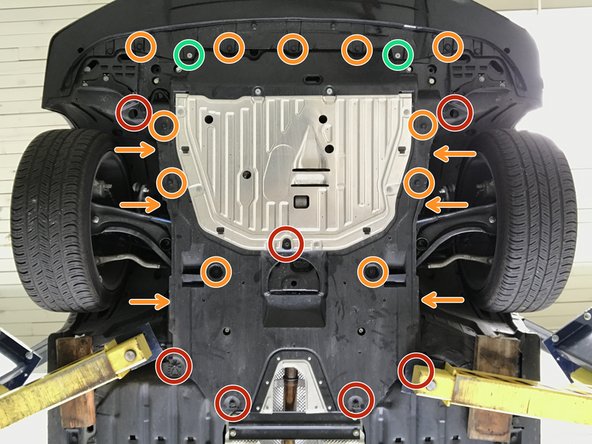
Locate the engine skidtray to gain access to the downpipe and front-pipe
-
Use 5mm Allen to remove the two (2) bolts shown in green circles
-
Use 10mm socket & ratchet to remove the seven (7) bolts shown in red circles
-
Use a flathead screwdriver to remove the seventeen (17) plastic push-clips. Orange arrows identify the push-clips described in the next step (3)
-
-
-
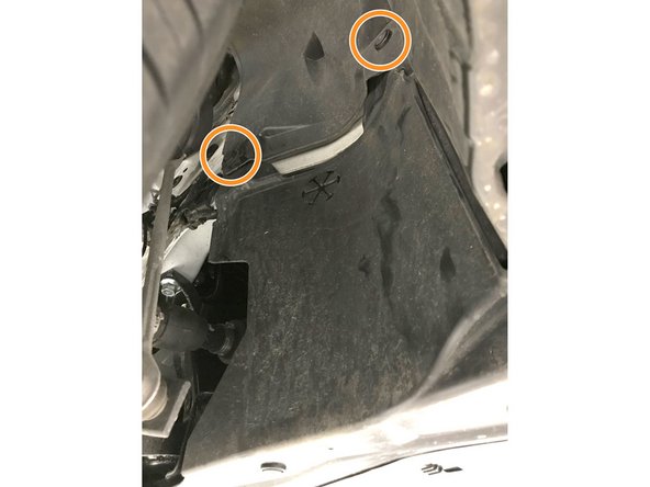
Use large flat head screw driver to remove push-clips on each side of skidtray
-
-
-
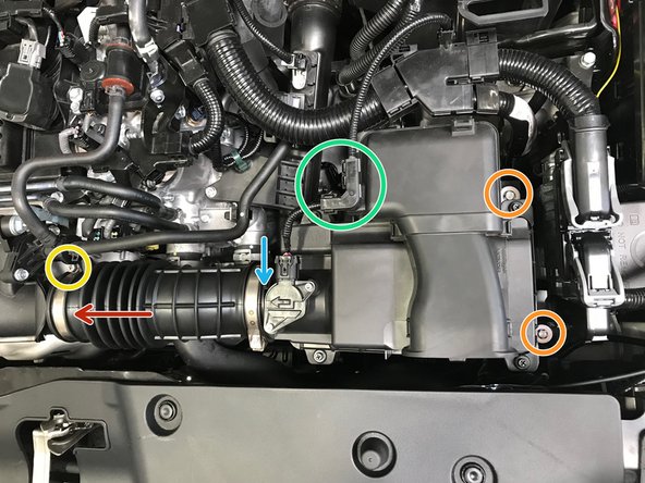
Disconnect the wiring harness from the MAF Sensor
-
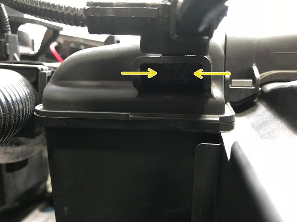
Remove the wire cover from the airbox
-
Use needle nose pliers to pinch the clips then pull the cover off the airbox
-
-
-
Use a 10mm socket, extension & ratchet to loosen the two (2) 10mm bolts
-
You can leave the bolts loose in position during airbox removal
-
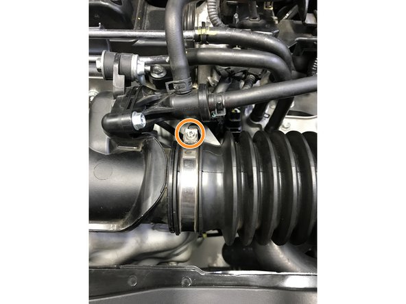
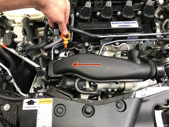
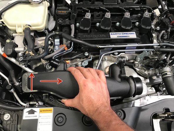
Use a 5.5mm socket to loosen the hose clamp
-
A small phillips screwdriver can be used, but is not recommend because the hose clamp head strips easily
-
-
-
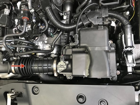
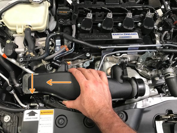
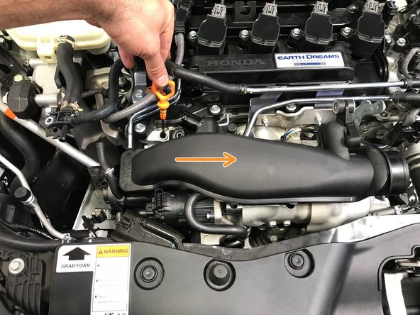
Pull the hose off the turbo inlet pipe in the direction of the arrow
-
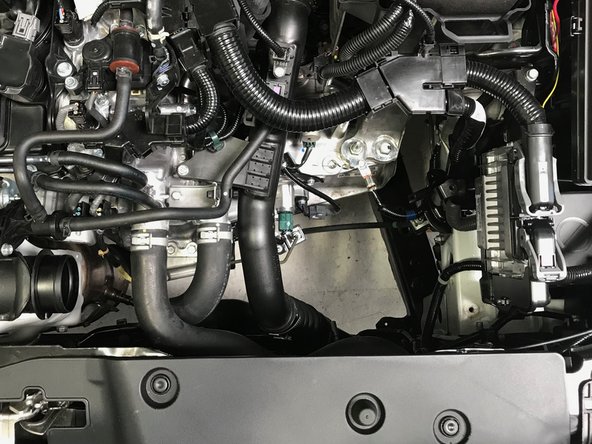
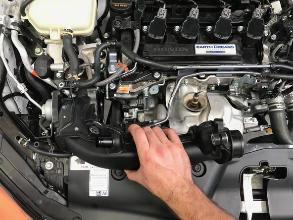
With the hose loose, remove the entire airbox from the engine bay
-
The result will look as shown in the second image
-
-
-
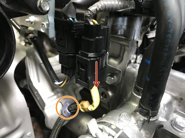
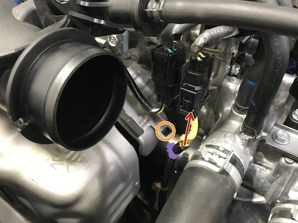
Disconnect the O2 sensor wire as shown with red arrow
-
Use small pliers to remove the purple clip from the bracket
-
Pinch the back side of the purple clip and push through the bracket
-
-
-
Verify that the bracket and radiator hose are not hot. If hot allow the vehicle to cool before proceeding
-
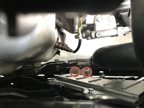
Moving the radiator hose allows improved clearance for downpipe removal
-
Use a 10mm socket & ratchet to remove the two (2) 10mm bolts holding the lower radiator hose in place
-
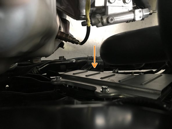
With the bolts removed, move the radiator hose upward and forward
-
-
-
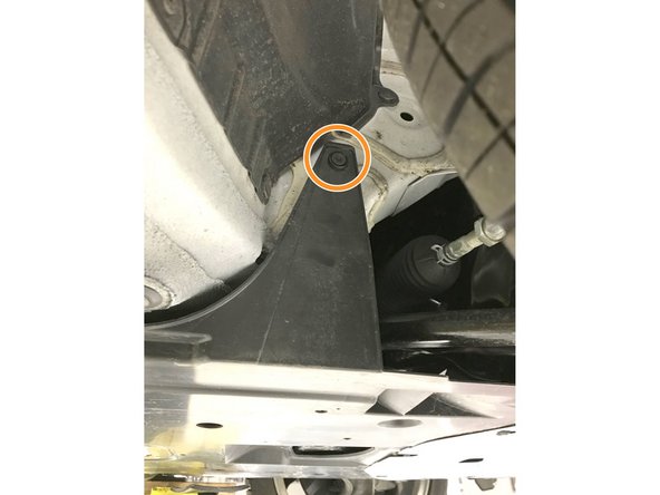
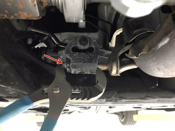
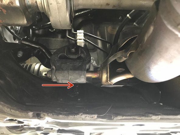
Apply a small amount of silicone spray to the end of the hanger rod (red arrow)
-
Use the tongue and groove pliers as shown to remove the rubber hanger
-
-
-
Use a 14mm socket and ratchet to remove the three OE nuts, these nuts/studs can be set aside as you will use the provided three (3) 15mm stud/nuts when reinstalling the downpipe
-
It is possible that the stud will thread out of the downpipe flange. This is not an issue. The stud can be threaded back into the flange like a bolt
-
-
-
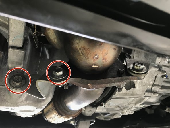
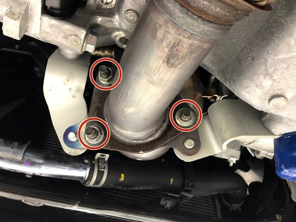
Verify that the brackets and coolant hose are not hot. If hot allow the vehicle to cool before proceeding
-
Use a 14mm socket & ratchet or wrench to remove the four (4) 14mm bolts as shown in red circles in two images
-
Remove the brackets from the vehicle
-
-
-
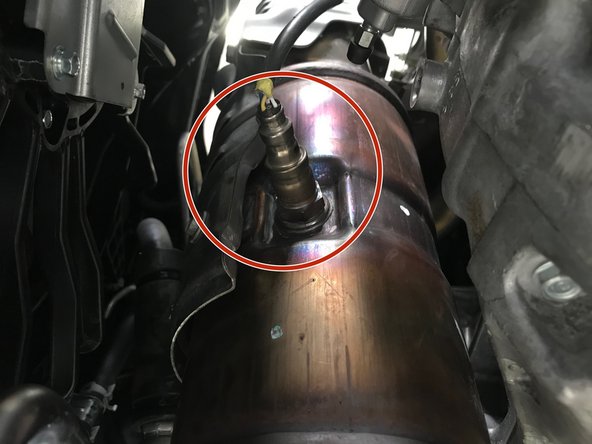
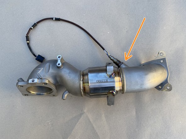
Locate the secondary O2 sensor on the downpipe
-
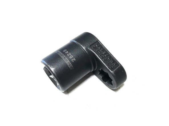
Locate the specialty socket - 22mm or 7/8" O2 sensor socket
-
Use the ratchet wrench in the specialty socket to remove the O2 sensor
-
-
-
Going forward we will reference the black plastic pipe connected to the turbo as the "Turbo Inlet Pipe (TIP)"
-
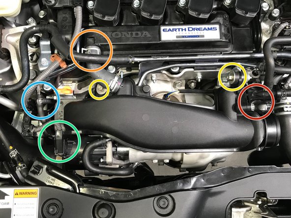
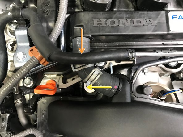
The following components are identified for clarity in the following steps
-
EVAP Bleed Air
-
Valve Cover Breather Hose
-
TIP Mounting Points
-
Waste Gate Actuator (WGA) Wiring Connection
-
By-Pass Valve (BPV) Hoses
-
-
-
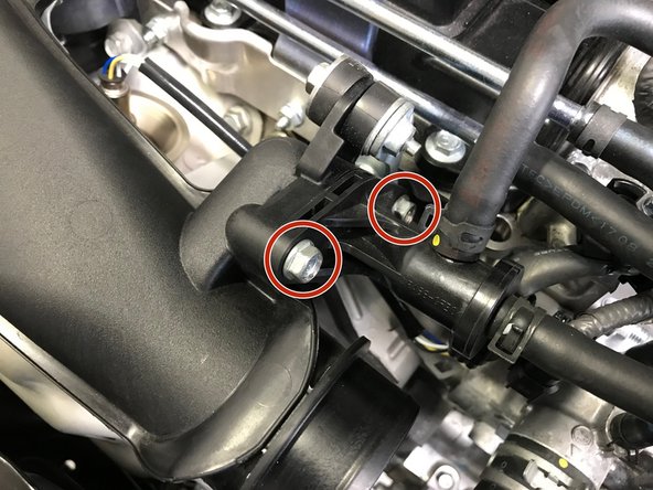
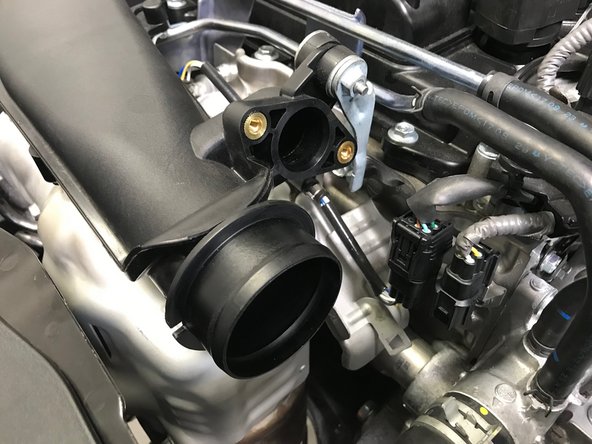
Use a 10mm socket & ratchet to remove the two (2) 10mm bolts
-
Pull the EVAP bleed air out of the TIP and set to the side
-
-
-
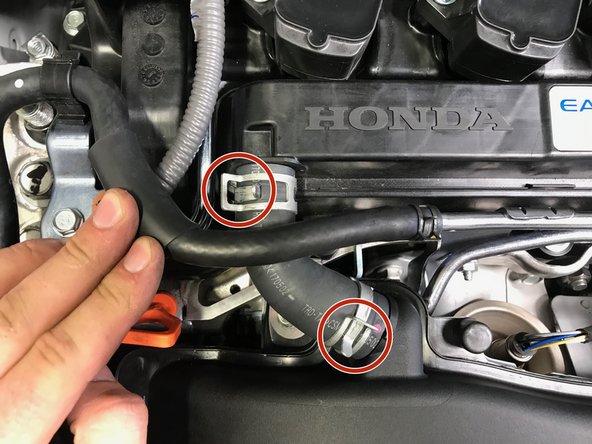
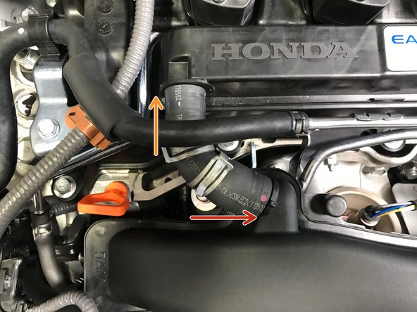
Use pliers to loosen the spring clamps. Slide the clamps towards the center of the hose
-
Pull the hose off the valve cover first
-
Pull the hose off the TIP second
-
-
-
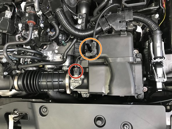
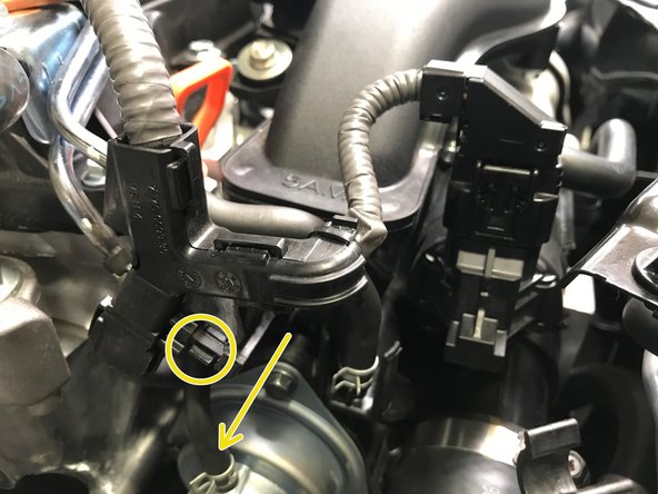
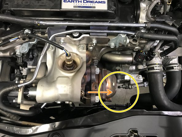
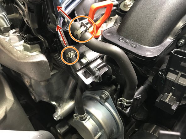
Disconnect the wiring from the Waste Gate Actuator (WGA)
-
Locate the wiring loom
-
Press down on the small tab and pull the wiring loom from the bracket in the direction of the yellow arrow
-
Move the wiring harness towards the rear of the car out of the way
-
-
-
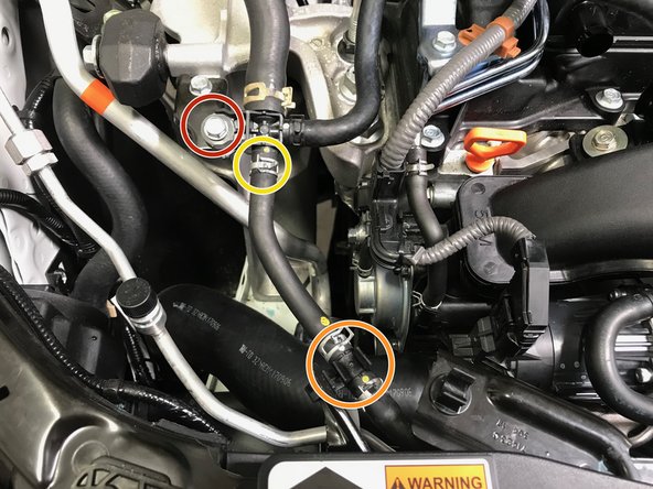
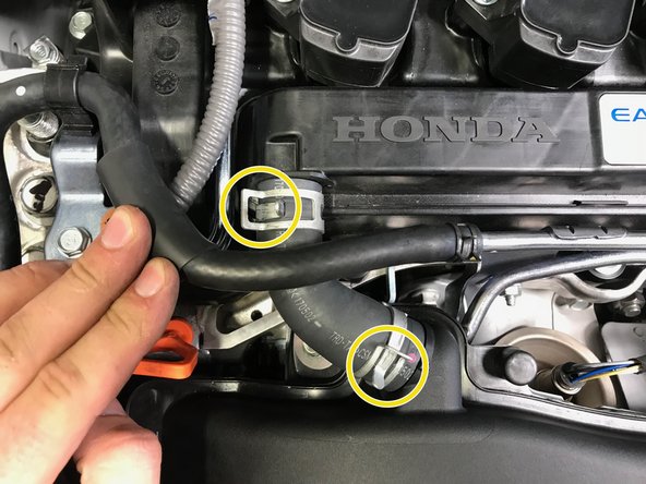
Use pliers to loosen the spring clamps. Slide the spring clamps with red circles towards the center of the hose
-
Pull the BPV hoses off the metal tubes in the direction of the orange arrows
-
-
-
Use pliers to loosen the spring clamp. Slide the clamp towards the center of the of the hose
-
Do not remove the hose yet
-
Pop the hose out of the plastic clip
-
Pull the hose off the plastic "T". Move the hose towards the front of the car out of the way
-
Some coolant may spill from the hose and "T" connection
-
Use a 10mm socket & ratchet to remove the bolt holding the "T" connection
-
-
-
Use a 10mm socket & ratchet or Phillips screwdriver to loosen the worm-gear clamp
-
Pull the hose off the TIP in the direction of the arrow
-
Remove the clamp from the hose so it does not get lost in the engine bay
-
Bend the hose towards the rear of the car. Stuff it into the fender liner out of the way
-
-
-
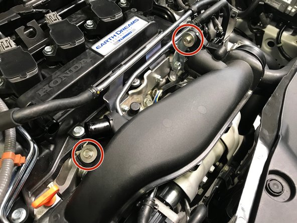
Use a 10mm socket & ratchet to remove the two (2) TIP mounting bolts
-
-
-
The next process is to remove the Turbo Inlet Pipe (TIP) from the vehicle.
-
We will first identify the hardware location and how to remove without losing the hardware in the engine bay
-
Second, we will show step by step images of physically removing the TIP for PDF users and a quick video for mobile users
-
-
-
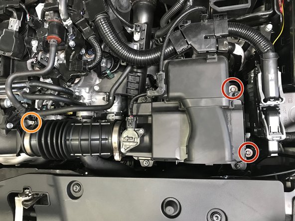
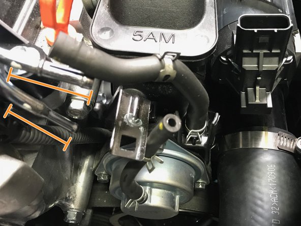
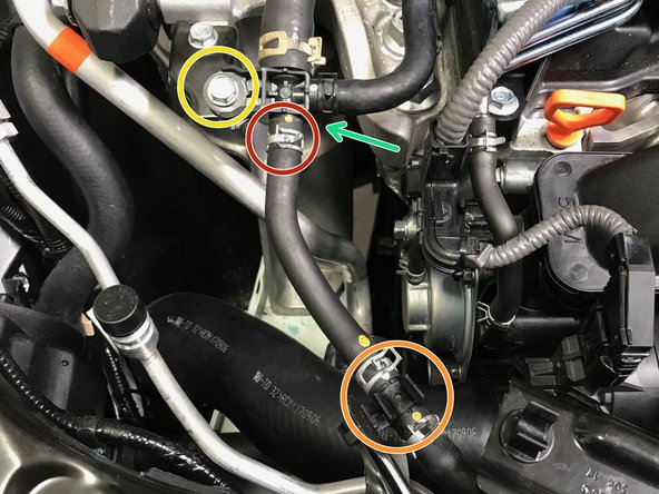
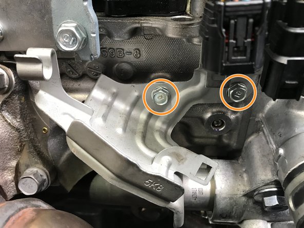
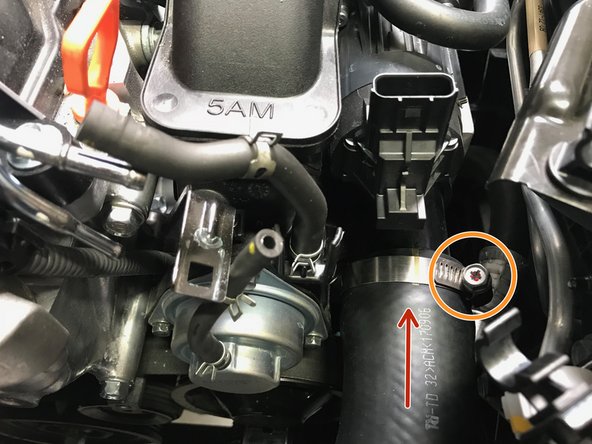
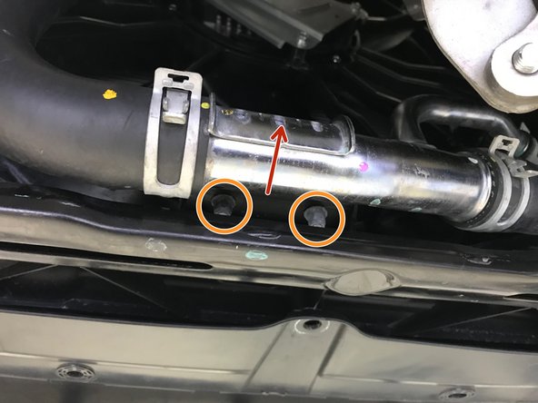
Locating the mounting hardware on the TIP can be difficult. Please see the second image for clear identification
-
The hardware circled in red are bolts. The hardware circled in orange is a nut on a stud
-
Use a 12mm socket, extension & ratchet to loosen the three (3) bolts
-
Use a 12mm socket, extension & ratchet to loosen one (1) nut
-
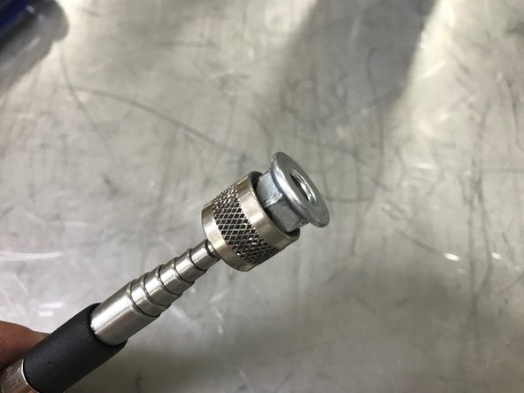
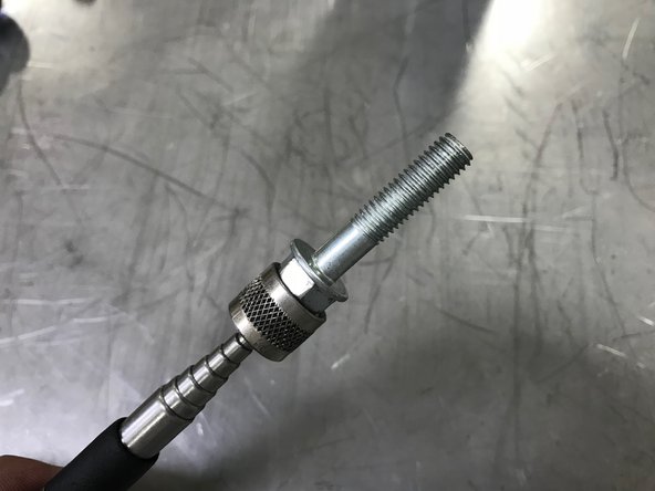
With the bolts loose, but not removed, use the magnet on a stick to remove the bolts from the TIP
-
-
-
Mobile Users proceed to Step 24 for video tutorial
-
Pull the oil dip stick out a couple inches and flex out of way
-
Move the TIP towards the passenger side of the vehicle past the oil dip stick
-
Reinstall the oil dip stick
-
Move the TIP further towards the passenger side of the vehicle and begin to rotate the top of the TIP towards the front of the vehicle
-
Continue the rotation of the TIP while moving the TIP up and out of the engine bay
-
-
-
Pull the oil dip stick out a couple inches and flex out of way
-
Move the TIP towards the passenger side of the vehicle past the oil dip stick
-
Reinstall the oil dip stick
-
Move the TIP further towards the passenger side of the vehicle and begin to rotate the top top of the TIP towards the front of the vehicle
-
Continue the rotation of the TIP while moving the TIP up and out of the engine bay
-
-
-
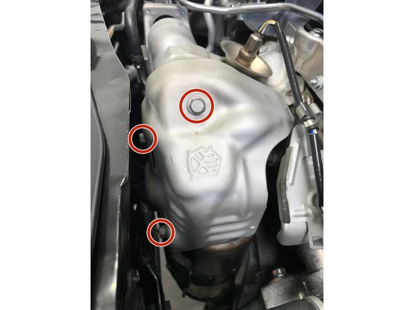
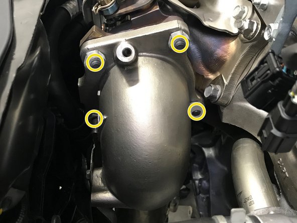
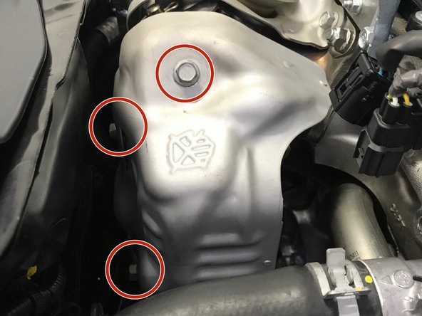
Verify that the heat shield is not hot. If hot allow the vehicle to cool before proceeding
-
Use a 12mm wrench to remove the three (3) 12mm bolts
-
Remove the heat shield from the engine bay
-
-
-
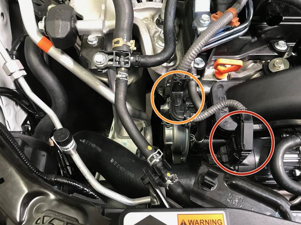
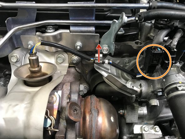
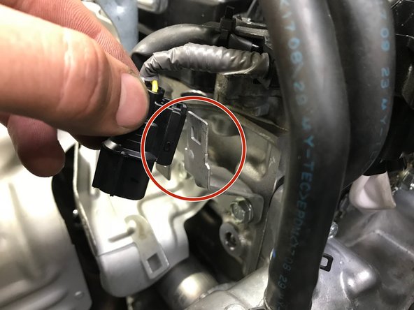
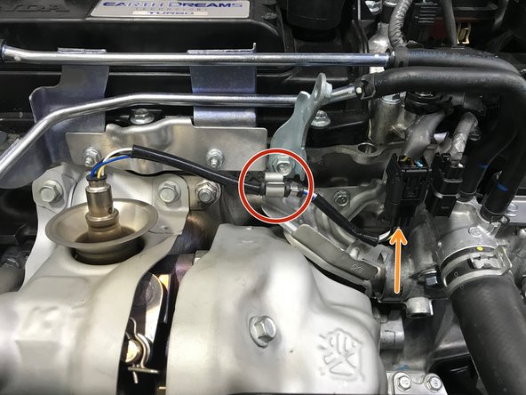
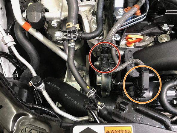
Pull the wire out of the bracket as shown with the red arrow
-
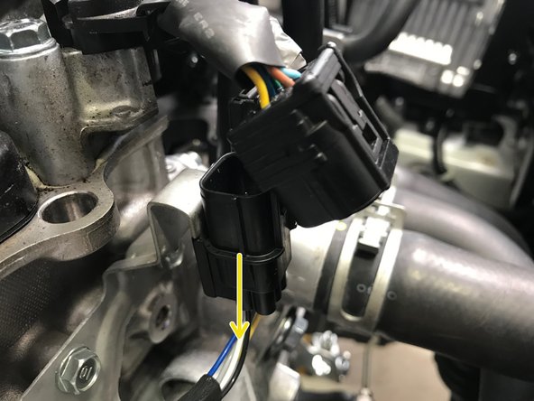
Disconnect the wiring circled in orange
-
Press a tab on the back of the wiring connection and pull down off the bracket as shown in second image
-
Move the primary O2 sensor wire to the side out of the way
-
-
-
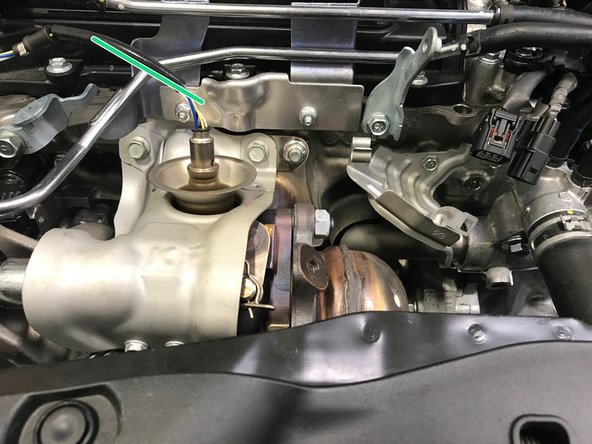
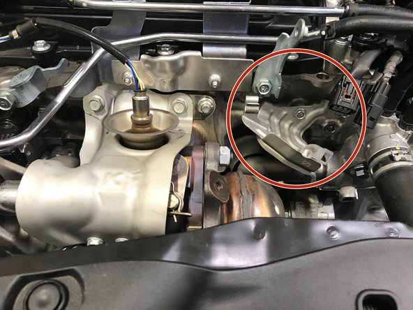
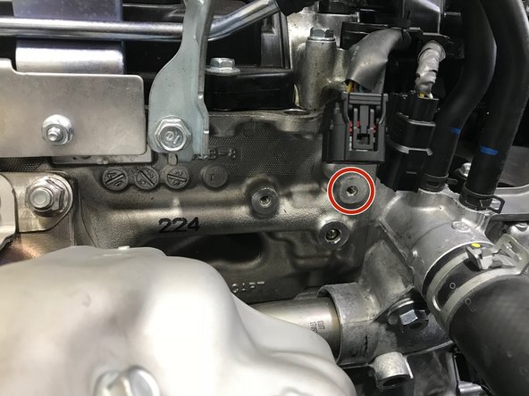
Locate the wiring bracket to the driver's side of the turbo
-
Use a 10mm socket & ratchet to remove the two (2) 10mm bolts
-
Remove the bracket from the vehicle
-
-
-
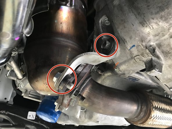
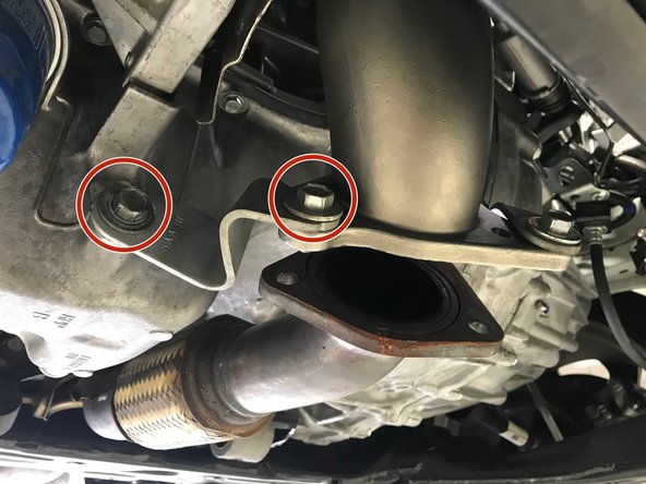
It may be necessary to spray the studs/bolts with a penetrating lubricant before removal. Apply lubricant if needed and let sit for a few minutes then attempt removal
-
Use a 14mm socket & ratchet to remove the two (2) nuts and two (2) bolts
-
Move the downpipe off the studs towards the driver's side
-
Lower the downpipe straight down through the opening below
-
-
-
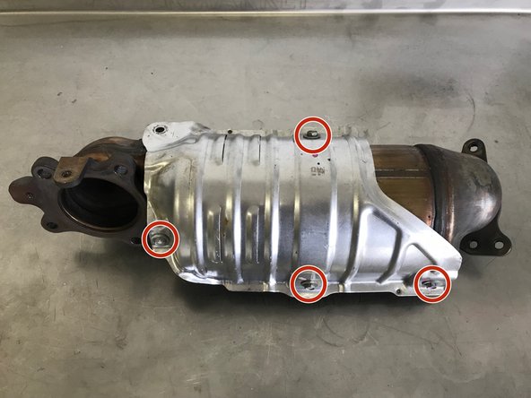
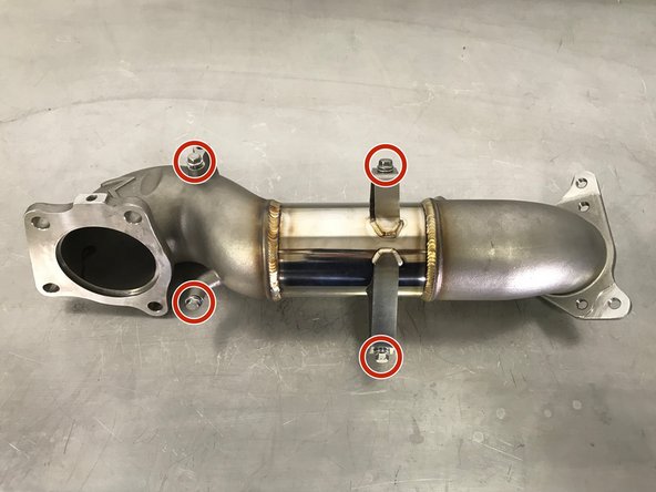
Use a 10mm socket & ratchet to remove the four (4) bolts
-
-
-
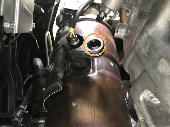
Use the specialty O2 sensor socket to install the secondary O2 sensor into the defouler. Torque to 30-33 ft-lbs
-
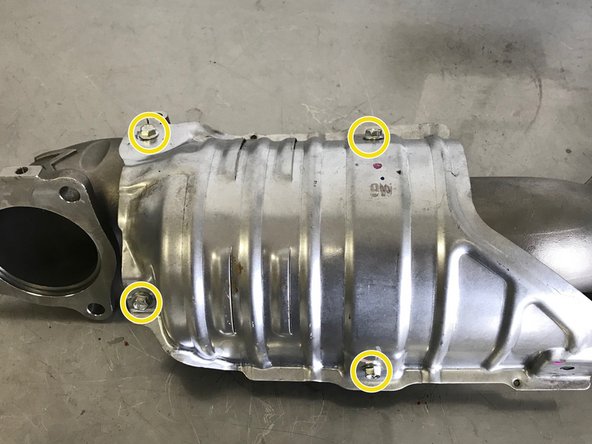
Locate the four (4) provided 10mm flange bolts on the downpipe
-
Use a 10mm socket and torque wrench to install the provided four (4) 10mm flange bolts and heat shield. Torque to 12-15 ft-lbs
-
-
-
In the situation that an OE stud or nut was damaged during downpipe removal, you may use a M10x1.25 stud or nut for replacement
-
Use a 14mm socket & torque wrench to install the four (4) OE studs/nuts. Torque to 42-48 ft-lbs
-
-
-
Use a 12mm wrench to install the three (3) 10mm bolts and heat shield. Torque to 15-19 ft-lbs
-
Some aftermarket downpipes may not have the provision for this heat shield
-
-
-
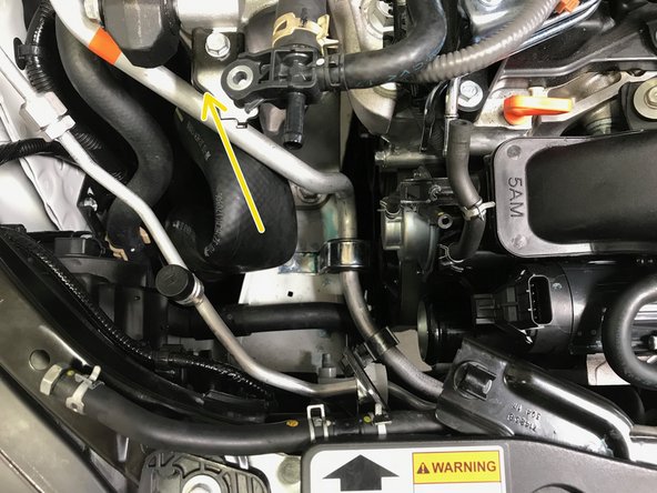
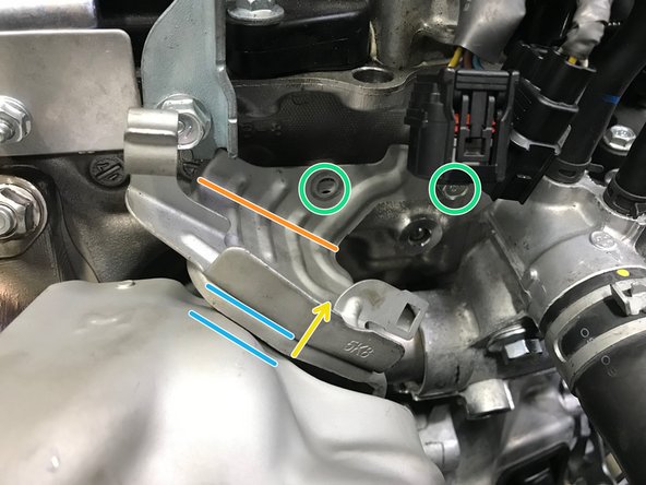
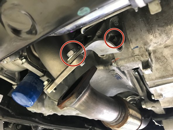
Install the bracket and hand tighten one (1) 10mm bolt into the engine shown with the red circle
-
The wiring bracket will need to be bent up slightly to clear the downpipe heat shield.
-
Bend the wiring bracket along the orange line in the direction of the yellow arrow until there is clearance
-
Clearance will require the bracket to be bent upward approximately 10mm
-
Use a 10mm socket & torque wrench to install the two (2) 10mm bolts and bracket. Torque to 8-10 ft-lbs
-
After tightening the bolts, verify there is a small clearance gap between the bracket and heat shield
-
-
-
Install the secondary O2 sensor wiring harness onto the bracket
-
Install the primary O2 sensor wiring harness onto the bracket
-
-
-
Install the primary wire into the metal clip
-
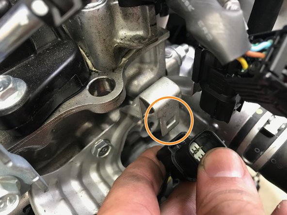
Connect the primary sensor to the wiring harness as indicated by orange arrow
-
-
-
Installation of the TIP follows the same process for removal in reverse
-
Lower the TIP into the engine bay with the TIP rotated towards the front of the car
-
Rotate and lower the TIP into the engine bay then move it towards the driver's side of the engine bay
-
Pull the oil dip stick out a couple inches and flex out of way
-
Move the TIP further to the driver's side while sliding the TIP over the stud in the compressor housing
-
Reinstall the oil dip stick
-
-
-
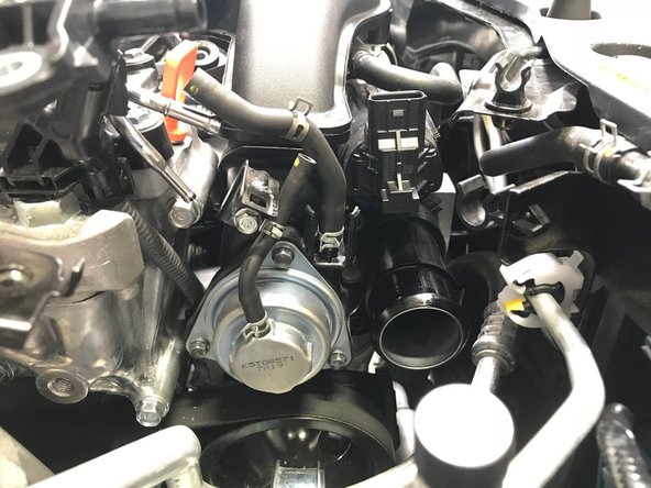
With the TIP loosely in position on the turbo, we will begin the most frustrating part of the entire installation.
-
Using the Magnet on a Stick we can loosely thread the nut onto the stud and the bolts into the compressor housing without the risk of losing the hardware in the engine bay
-
-
-
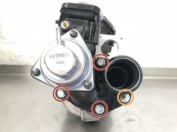
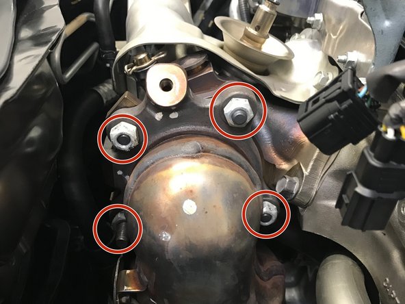
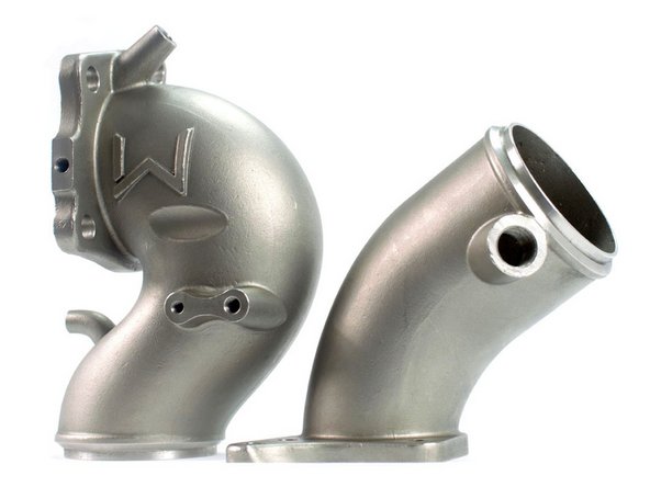
An installed TIP is shown out of the car for clarity
-
The three (3) red circles show the locations of the 12mm bolts
-
The orange circle shows the location of the 12mm nut and stud
-
Use the magnet on a stick tech tip shown in Step 37 to first loosely install the bolts and nut
-
Tighten the hardware and torque to 15-19 ft-lbs
-
-
-
Use a 10mm socket & torque wrench to install the two (2) TIP mounting bolts. Torque to 8-10 ft-lbs
-
-
-
Pull the hose out and reinstall the band clamp in the same orientation it came off
-
Push the hose onto the TIP in the direction of the arrow
-
Use a 10mm socket & ratchet or Phillips screwdriver to tighten the worm-gear clamp until snug
-
-
-
Use a 10mm socket to install the bolt holding the "T" connection. Torque to 8-10 ft-lbs
-
Pop the hose into the plastic clip
-
Push the hose onto the plastic "T". Use pliers to install the spring clamp at the end of the coolant hose around the "T" connection
-
-
-
Push the BPV hoses onto the metal tubes in the direction of the red arrows
-
Use pliers to install the spring clamps onto the end of the hoses around the metal pipe
-
-
-
Install the wiring harness back onto the bracket
-
Reconnect the wiring harness to the WGA
-
-
-
Push the hose onto the TIP first, following the red arrow.
-
Push the hose onto the valve cover second
-
Use pliers to install the spring clamps onto the end of the hose
-
-
-
Use a 10mm socket & torque wrench to install the two (2) 10mm bolts. Torque to 8-10 ft-lbs
-
-
-
Move the radiator hose back into the correct position so the bolt holes and bracket holes align
-
Use a 10mm socket & torque wrench to install the two (2) 10mm bolts holding the lower radiator hose in place. Torque to 8-10 ft-lbs
-
-
-
Use a 14mm socket or wrench to install the four (4) 14mm bolts and brackets. Torque to 38-42 ft-lbs
-
Use of the lower mounting brackets are necessary for the proper support of the downpipe
-
Failure to install these brackets can result in failure of downpipe
-
-
-
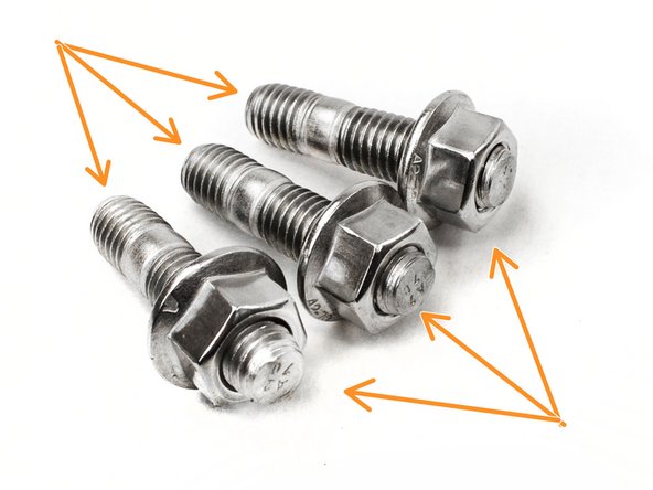
Locate the three (3) provided M10 flange nuts and the three (3) provided M10 studs
-
Use a 15mm socket & torque wrench to install the three (3) 15mm nuts/studs provided. Torque to 30-40 ft-lbs
-
Please note that the photo of the part installed on the car shows OEM hardware being used but this is not the case with current production parts.
-
-
-
Apply a small amount of silicone spray to the end of the hanger rod
-
Push the rubber hanger onto the hanger rod
-
-
-
Connect the O2 sensor to the wiring harness
-
Install the purple clip into the wiring bracket
-
-
-
Lower the airbox assembly into the engine bay
-
Install the induction hose onto the TIP
-
Use a 10mm socket and torque wrench to install the two (2) 10mm bolts that hold the airbox assembly. Torque to 3-4 ft-lbs
-
Use a 5.5mm socket or phillps screwdriver to tighten the band clamp until snug
-
Install the wiring harness into the airbox
-
Reconnect the MAF sensor wiring
-
-
-
Install the seventeen (17) plastic push-clips. Orange arrows identify the push-clips described in the next step
-
Use 10mm socket & torque wrench to install the seven (7) bolts shown in red circles. Torque to 8-10 ft-lbs
-
Use 5mm Allen and torque wrench to install the two (2) bolts shown in green circles. Torque to 8-10 ft-lbs
-
-
-
Install the remaning six (6) push-clips on each side of the skidtray
-
-
-
Defouler & Non-Catted Downpipes are strictly intended for racing use only. Installation and use are at the customers own risk
-
Some smell may be present on the first start as any residue on the downpipe burns off. This is normal and will not happen after the 1st heat cycle.
-
To get the best performance from your Performance Downpipe, we highly recommend a custom tune.
-
A custom tune for your specific vehicle with your specific modifications will provide the best performance for your Civic and the location you live in
-
-
-
This completes the installation of your 27WON Performance Downpipe
-
If you are installing a 27WON Front-Pipe along with the Downpipe, please see the Front-Pipe Instructions Here: http://store.27won.com/support/instructi...
-
We hope you were impressed with your 27WON experience and love your new Downpipe for years to come. Email us at sales@27won.com or call us at 571-271-0271 with any questions or concerns
-
Please Leave a review here: https://store.27won.com/10th-gen-civic-p...
-
Share your experience using #27WON on Instagram and Facebook
-