Introduction
In this installation guide we have provided step by step instructions to remove the OEM Intercooler, setup, and install the 27WON Performance Intercooler.
Advisory:
- Working under the vehicle requires a safe and sturdy location for the vehicle to sit on jackstands.
- The engine bay will be hot after recent vehicle operation. Allow the vehicle to cool or use a fan to cool the engine bay before working on the vehicle.
- Removing the bumper is very difficult to do by yourself and can result in scratches to the paint or headlights. We strongly encourage using a friend's help during bumper removal and installation.
- Trimming the rubber OEM intercooler shrouds is necessary for 27WON Intercooler fitment. This is easy and can be done with scissors.
Tools
- 3/8" Ratchet
- 3/8" Torque Wrench
- 3/8" Long Extension
- 8mm Socket
- 10mm Socket
- 12mm Socket
- 10mm Wrench
- 5mm Allen Key
- Flat Head Screwdriver - Large
- Flat Head Screwdriver - Small
- Phillips Screwdriver - Small
- Phillips Screwdriver Short Shank
- Assorted Plastic Interior Trim Removal Tools
- Masking Tape
- Hydraulic Jack
- Jack Stand × 2
- Needle Nose Pliers
Parts
- L15 Intercooler
- L15 2.25" Hot Side Pipe
- L15 2.75" Cold Side Pipe
- 28" Weather Stripping Seal
- L15 Hot Side Turbo Outlet Silicone
- L15 Hot Side IC Inlet Silicone
- L15 Cold Side IC Outlet Silicone
- L15 Throttle Body Silicone
- T-Bolt Clamp - 51-59mm
- T-Bolt Clamp - 63-71mm × 2
- T-Bolt Clamp - 67-75mm × 3
- T-Bolt Clamp - 86-94mm × 2
- M6x1.0x20mm Flange Bolt × 2
-
-
First and foremost; THANK YOU for becoming a part of the 27WON Family. We hope to REDEFINE your experience of the aftermarket with the highest level Parts, Customer Service, Packaging, & Support
-
-
-
Please reference the installation instructions for the intake system you have installed in your Civic
-
For 27WON Cold Air Intake please reference these instructions: https://store.27won.com/support/instruct...
-
Remove intake system from the vehicle
-
The prototype 27WON Turbo Inlet Pipe is installed on this vehicle, but does not affect the installation of the Front Mount Intercooler & Piping Upgrade
-
-
-
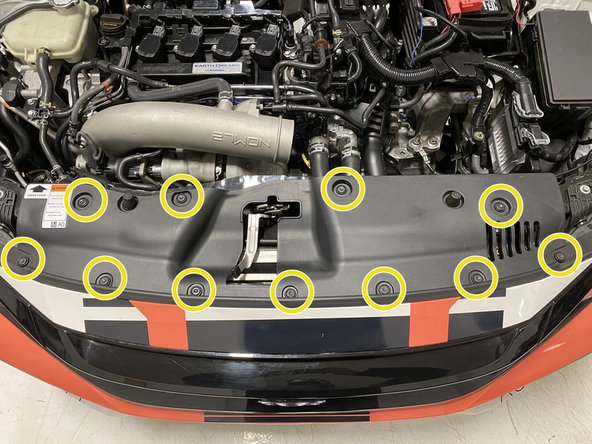
Remove the eleven (11) push clips that attach the radiator cooling panel to the vehicle using a flathead screwdriver or push clip removal tool
-
Remove the upper radiator panel from the vehicle
-
Starting on the driver's side, remove the four (4) push clips that connect the hood weather stripping to the bumper using a flathead screwdriver or trim removal tool
-
There are three small push clips, one medium push clip, and one large push clip. Note their positions for reinstallation
-
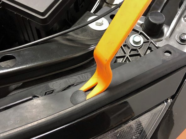
The small push clips can be difficult to remove with just a screwdriver. We recommend an interior trim removal tools used as shown in image 3
-
Remove the similar five clips on the passenger side of the vehicle
-
-
-
Remove the hood weather stripping and set it aside
-
Raise the vehicle and support with jackstands in the OE recommended locations
-
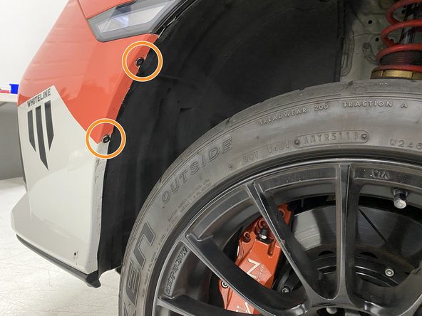
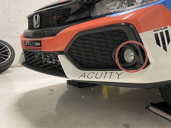
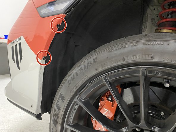
Look into the driver's side fender, in front of the front tire. Remove the two (2) phillips head screws that attach the bumper to the fender liner
-
The screws can be difficult to remove due to the tire being in the way. You can turn the wheel or use a short shank screwdriver
-
Remove the similar screws on the passenger side of the vehicle
-
-
-
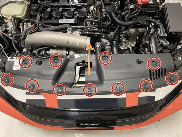
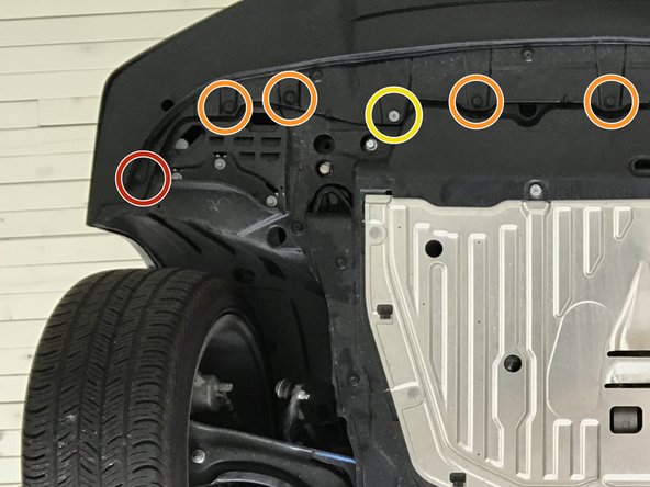
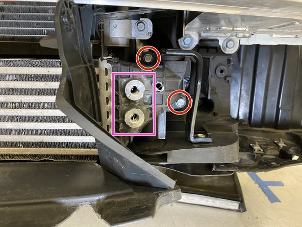
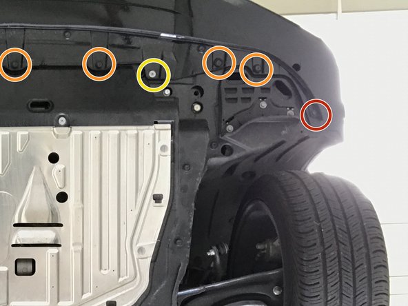
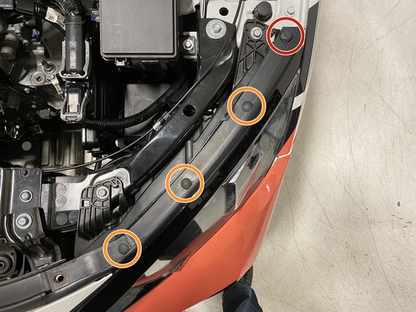
Use 10mm socket & ratchet to remove the two (2) bolts shown in red circles
-
Use a flathead screwdriver to remove the seven (7) plastic push-clips
-
Use 5mm Allen to remove the two (2) bolts shown in yellow circles
-
-
-
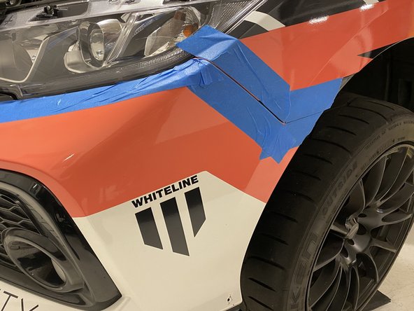
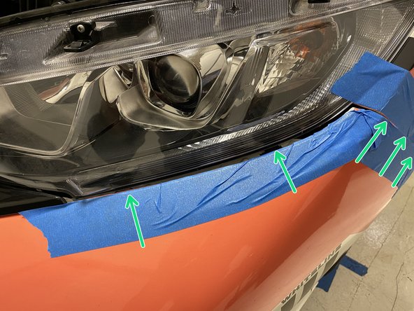
Now is a good time to apply tape to protect your paint from scratches during bumper removal and install
-
Apply masking or painters tape around the seams where the bumper meets the body of the car
-
-
-
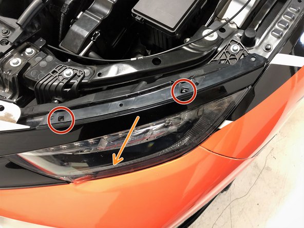
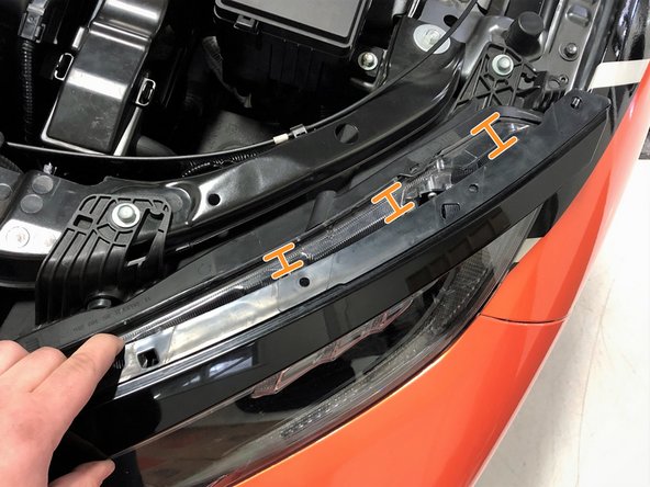
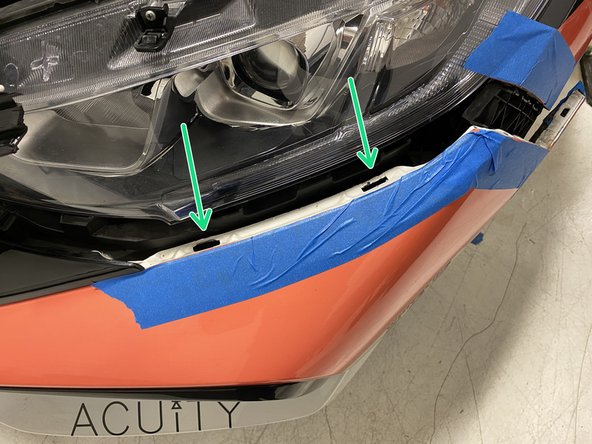
Using a small screwdriver, push down on the two tabs to release the upper headlight trim from the headlight on the driver's side
-
These tabs do not require very much pressure and can break if too much pressure is used. Pull outward slighly on the trim and you will feel the "pop" as each clip releases
-
The upper headlight trim will not be removed, it will only move outward as shown in image 2
-
Repeat these steps on the passenger side
-
-
-
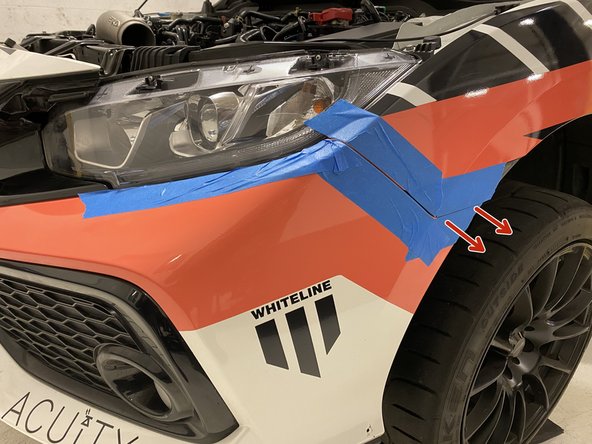
Starting at the corner of the bumper, pull outward until the corner pops free from the fender
-
The first time this is done can require a decent amount of force
-
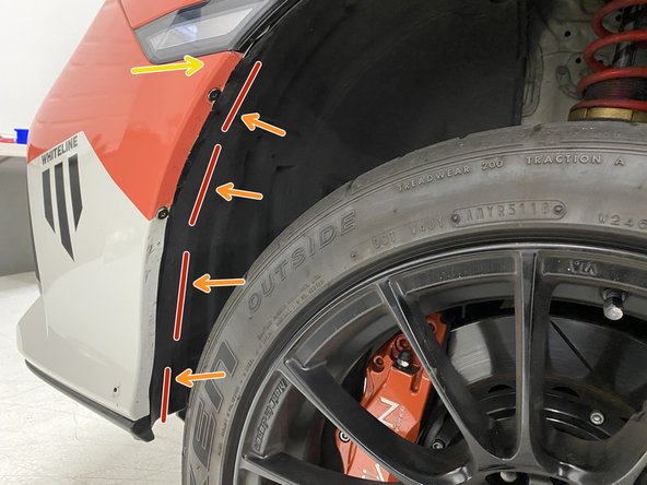
Keep pulling outward on the bumper and use a plastic interior trim tool to release the bumper from the three retaining clips by pushing on the retaining clips
-
The second image shows what you are looking for to push on. Take your time and take care to not damage the vehicle
-
Repeat these steps on the passenger side
-
-
-
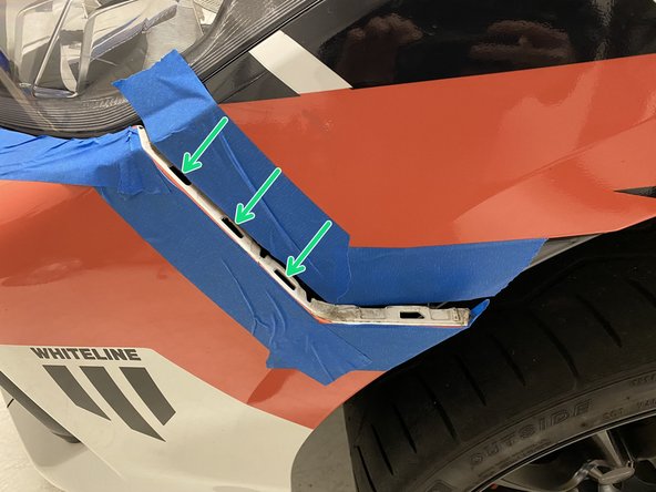
Moving along the headlight, keep pulling outward slightly
-
Using a plastic interior trim removal tool, lift up the two tabs to release them
-
The second image shows what you are looking for to lift upwards. Take your time and take care to not damage the vehicle
-
This side of the bumper will now be free from the vehicle. We recommend having a friend hold this side of the bumper while the other side is completed
-
Repeat these steps on the passenger side
-
-
-
The bumper will now only be held on by the fog light wiring
-
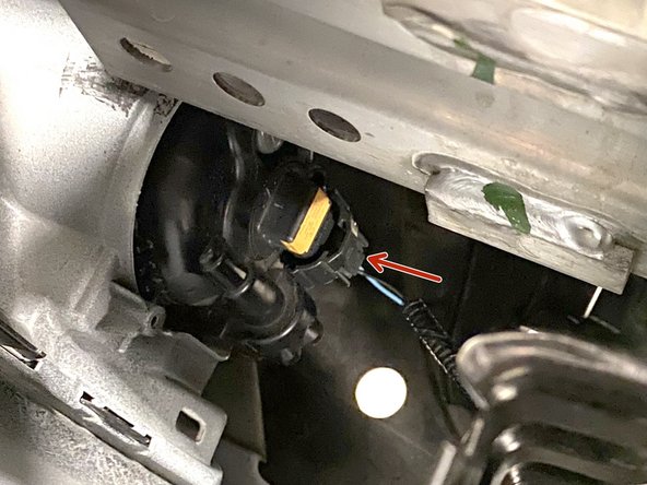
Pull the bumper forward and locate the wiring going to the fog light on the driver's side
-
Reach between the bumper and the rest of the vehicle. Unplug the fog light by squeezing the top and bottom of the plug
-
Repeat the prior two steps to unplug the passenger side fog light
-
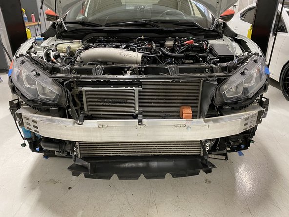
Remove the front bumper from the vehicle and place out of the way where it cannot get scratched or damaged
-
-
-
NOTE: the aluminum ports in the intercooler were added by 27WON for intercooler testing & validation. This will NOT be present on your vehicle
-
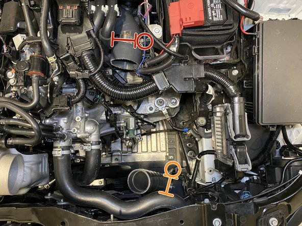
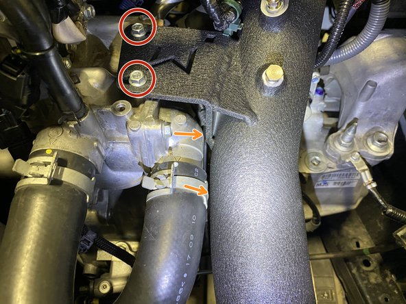
Remove the two (2) nuts using a 10mm socket & ratchet
-
Remove the two (2) bolts using a 10mm socket & ratchet
-
Remove the OEM lower hot pipe section from the vehicle
-
-
-
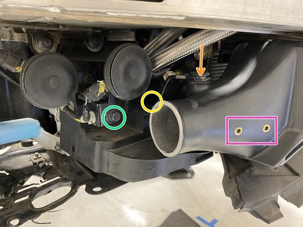
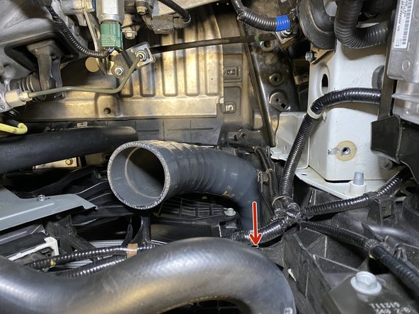
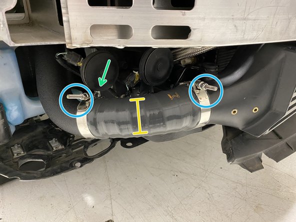
NOTE: the metal pipe section with brass plugs was added by 27WON for intercooler testing & validation. This will NOT be present on your vehicle
-
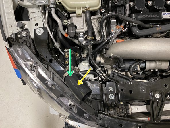
Loosen the band clamp holding the rubber hose to the turbo inlet pipe. Use a 10mm socket, ratchet & extension
-
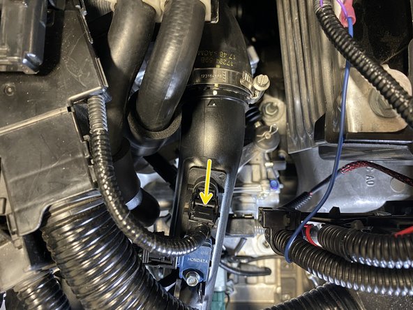
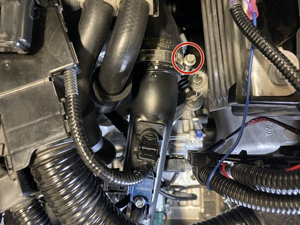
Loosen the bolt holding the OEM hot pipe to the chassis. Use a 10mm socket, ratchet & extension
-
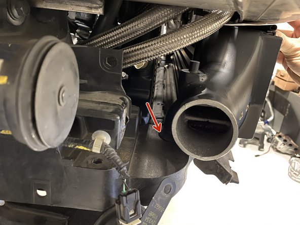
Slide the rubber hose off the turbo inlet pipe then rotate and bend out of the engine bay
-
With the rubber hose up and out of the engine bay, remove the entire hot pipe section from the vehicle
-
-
-
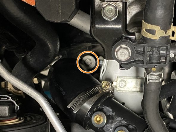
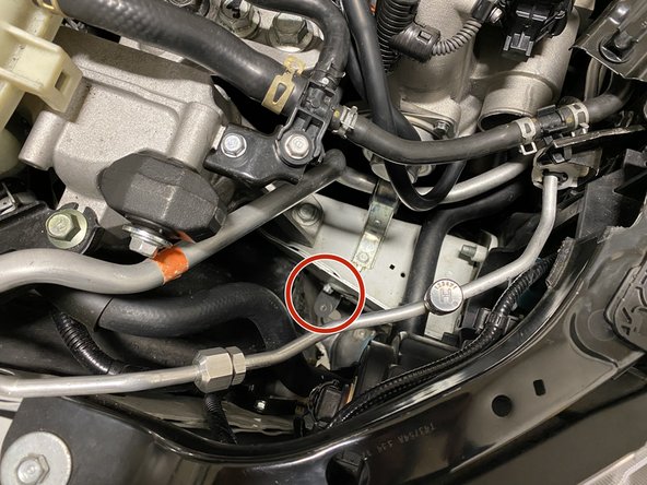
Remove the black metal bracket that supports the OEM hot pipe. Use a 10mm wrench
-
Remove black bracket
-
This bracket and bolt are not reused
-
-
-
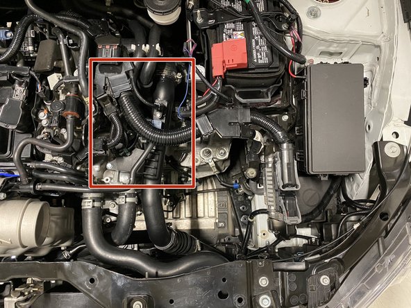
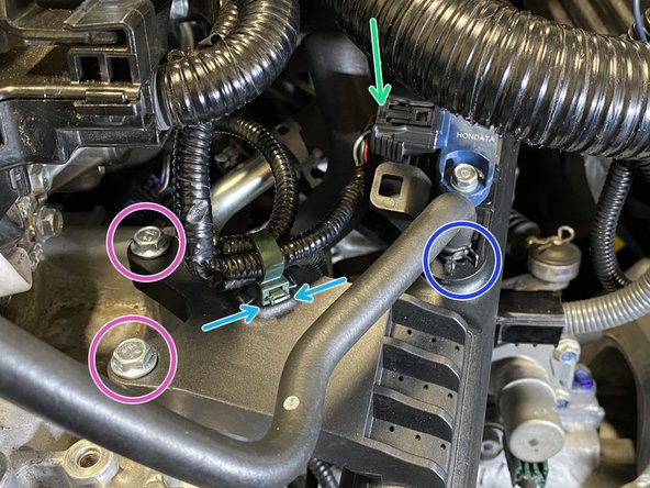
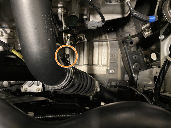
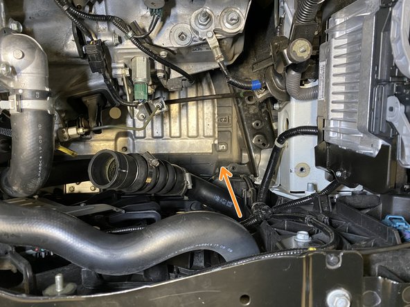
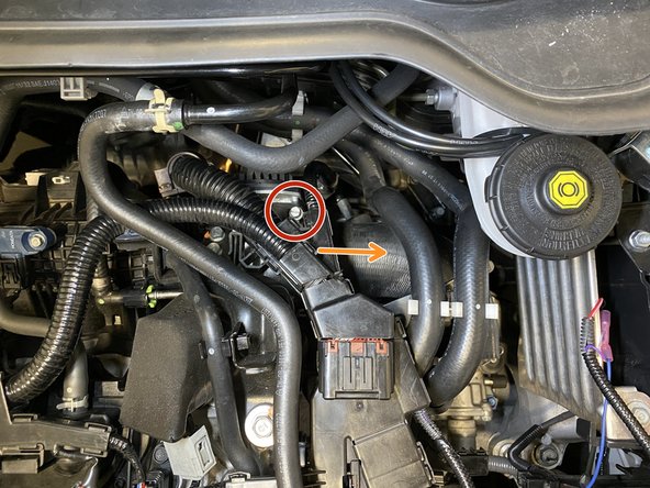
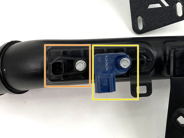
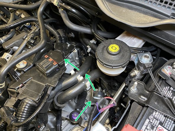
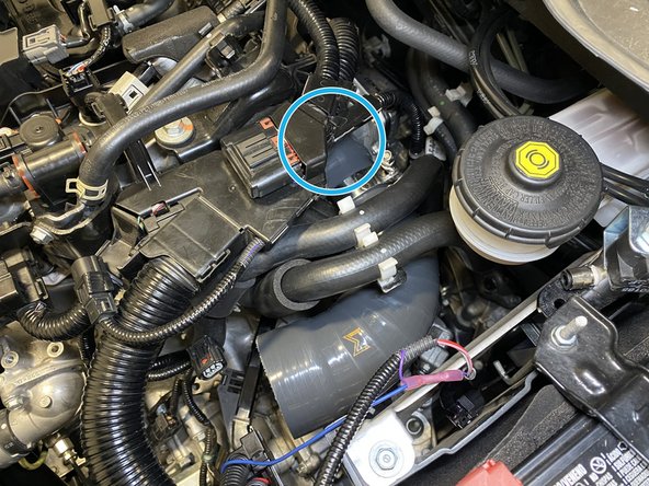
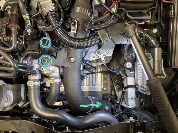
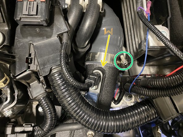
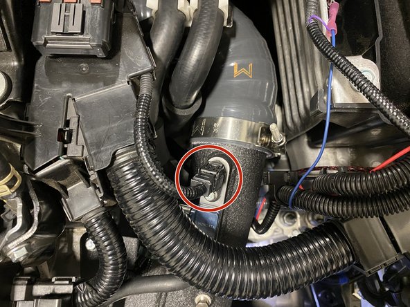
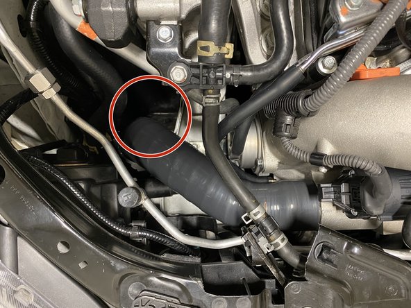
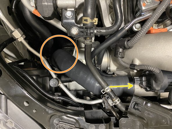
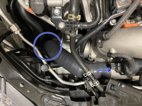
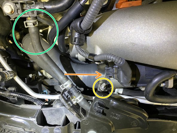
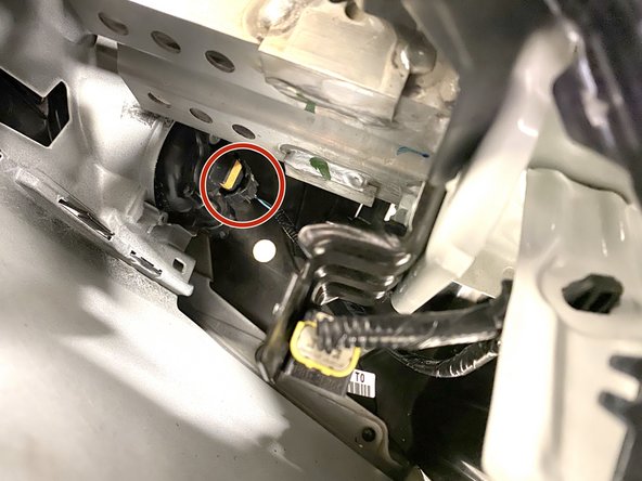
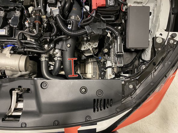
Locate area of the cold pipe highlighted
-
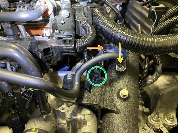
Un-clip the wiring from the temperature sensor
-
Un-clip the wiring from the MAP sensor
-
Remove the green wiring loom clip form the cold pipe bracket with needle nose pliers
-
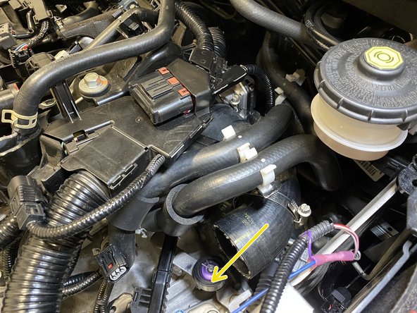
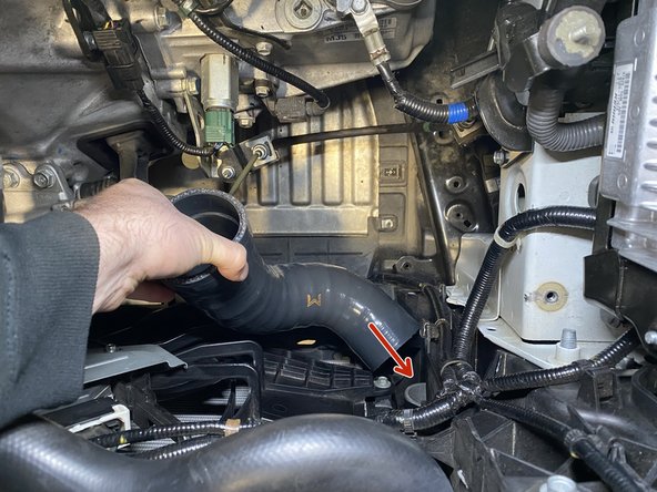
Loosen the spring clamp on the rubber hose using needle nose pliers then pull the hose off the cold pipe
-
Remove the two (2) bolts holding the cold pipe in place. Use a 10mm socket, ratchet, & extension
-
-
-
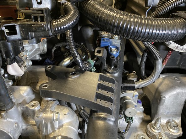
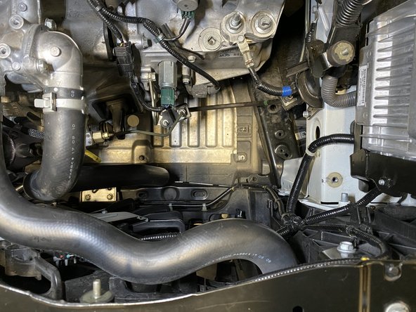
All parts shown disconnected
-
Loosen the band clamp with a flathead or 8mm socked and ratchet
-
Loosen the band clamp with a flathead or 8mm socked and ratchet
-
-
-
Slide the rubber hose off the bottom end of the cold pipe
-
Slide the cold pipe out of the throttle body hose
-
Remove the OEM cold pipe from the engine bay at set aside, the sensors will need to be transferred to the 27WON cold pipe in future steps
-
-
-
NOTE: the aluminum ports in the intercooler were added by 27WON for intercooler testing & validation. This will NOT be present on your vehicle
-
Remove the two (2) bolts using a 10mm socket & ratchet
-
Remove the OEM cold pipe lower section from the vehicle through the engine bay
-
-
-
Loosen the band clamp with a flathead or 8mm socked and ratchet
-
Slide the rubber hose off the throttle boddy
-
Remove the throttle body hose from the engine bay
-
-
-
Use a flathead screwdriver to remove the two (2) push clips
-
-
-
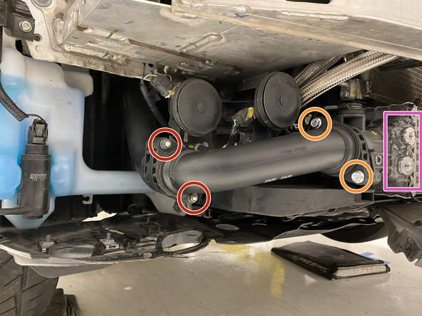
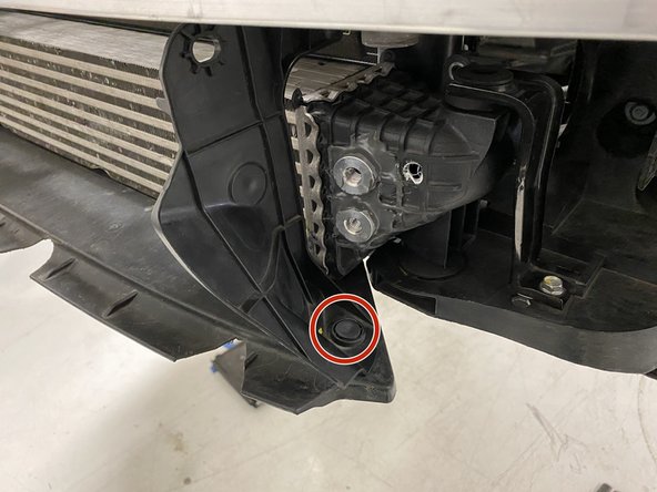
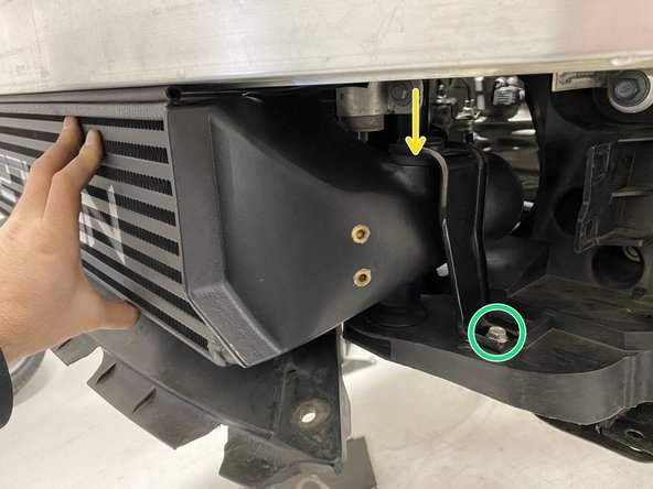
Remove the 12mm bolt from the OEM horn on the passenger side of the vehicle using a 12mm socket and ratchet
-
This helps you gain access to the bolt in the next step and with installation of the 27WON intercooler
-
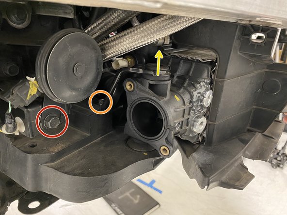
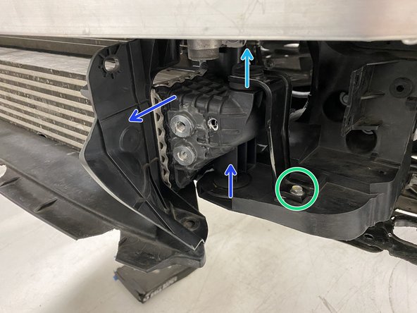
Remove the 10mm bolt from the OEM hot side mounting bracket on the passenger side of the vehicle using a 10mm socket and ratchet
-
Lift the bracket free from the vehicle
-
Remove the 10mm bolt from the OEM cold side mounting bracket on the driver's side of the vehicle using a 10mm socket and ratchet
-
Lift the bracket free from the vehicle
-
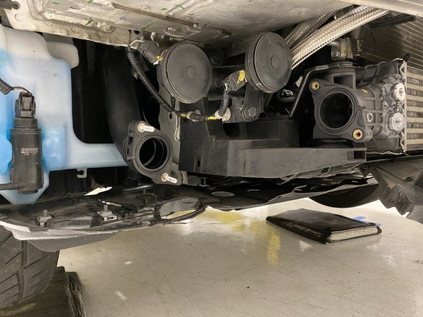
Lean the intercooler forward and lift out of the pockets it is sitting in
-
-
-
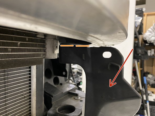
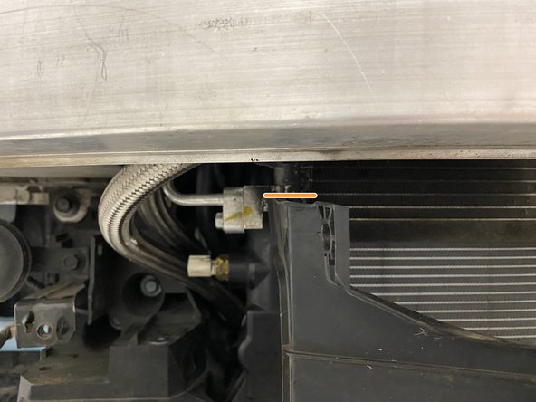
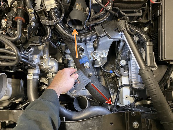
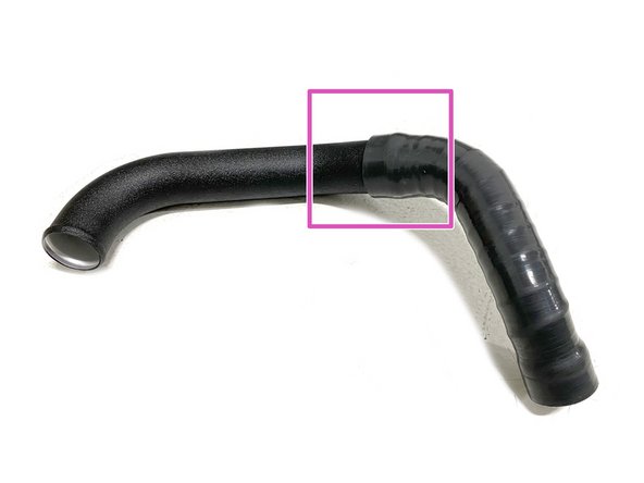
The OEM intercooler shrouds must be trimmed to fit the much larger 27WON intercooler
-
OEM Shroud shown with cut already
-
Cut along the orange line, this is flush with the underside of the crashbar
-
These are support ribs on the outer face of the shroud, you'll be cutting these
-
The section shown with the red arrow will fall away and is discarded after trimming
-
The remaining shroud will sit on top of the 27WON intercooler slightly. This is intentional to force good airflow through the intercooler and radiator
-
-
-
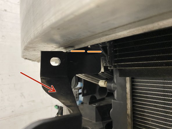
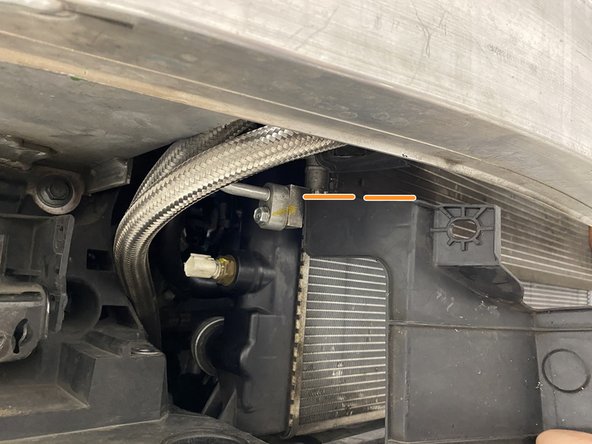
The OEM intercooler shrouds must be trimmed to fit the much larger 27WON intercooler
-
Cut along the orange line, this is flush with the underside of the crashbar
-
The section shown with the red arrow will fall away and is discarded after trimming
-
The remaining shroud will sit on top of the 27WON intercooler slightly. This is intentional to force good airflow through the intercooler and radiator
-
-
-
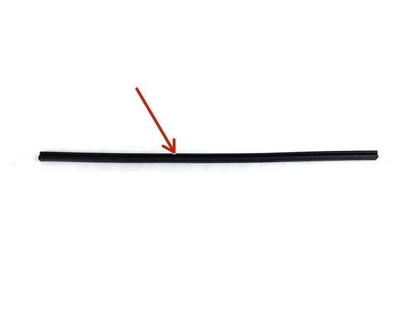
Provided foam seal already cut to length
-
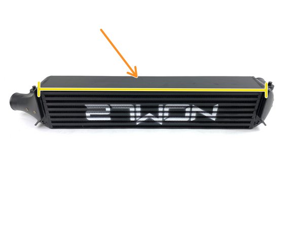
27WON Intercooler
-
The top plate of the intercooler protrudes outward approximately 1/4 inch for the seal to attach to
-
Place the seal onto the edge of the intercooler as shown
-
Center left and right on the intercooler
-
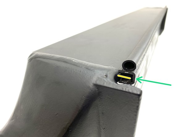
You want the round portion of the weatherstripping facing upwards to seal against the OEM crashbar to ensure good airflow through the intercooler
-
-
-
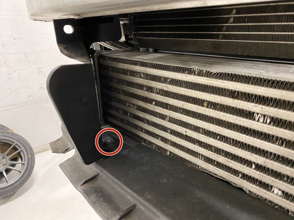
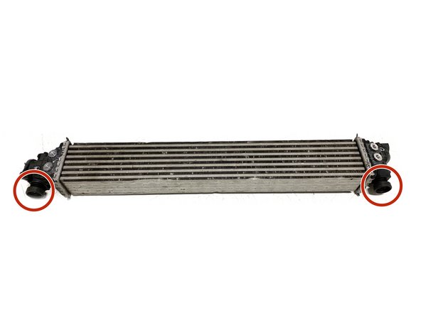
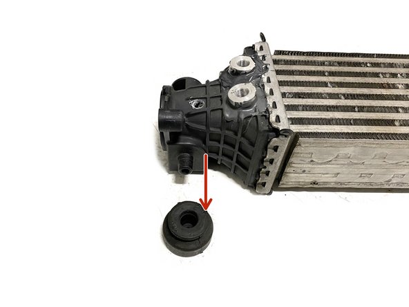
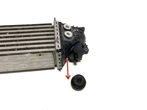
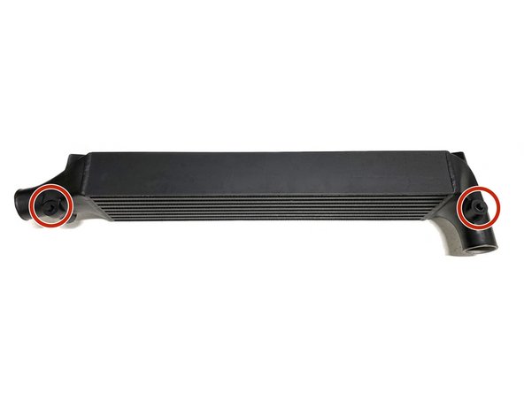
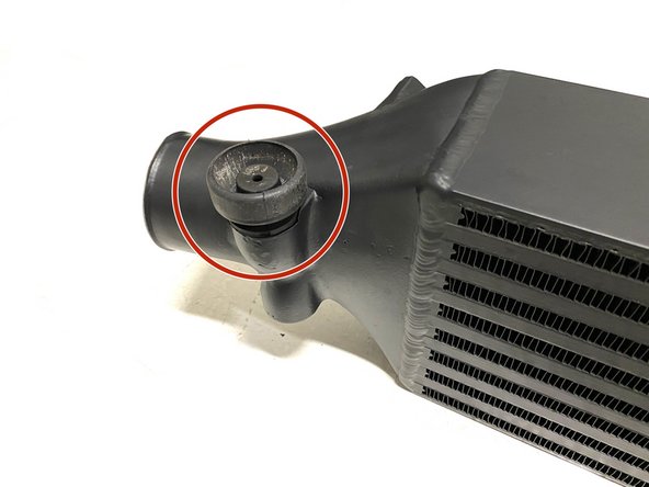
Remove the two (2) OEM rubber mounts from the bottom of the intercooler
-
-
-
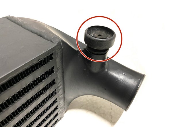
Install the rubber mounts onto the bottom mounting pegs of the 27WON intercooler as shown
-
-
-
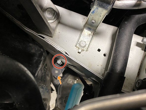
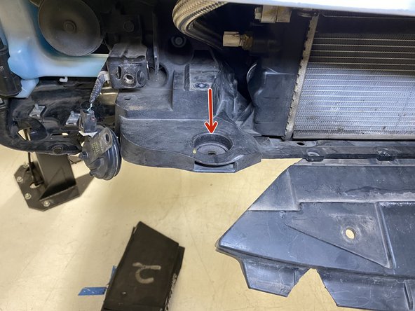
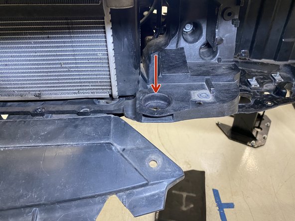
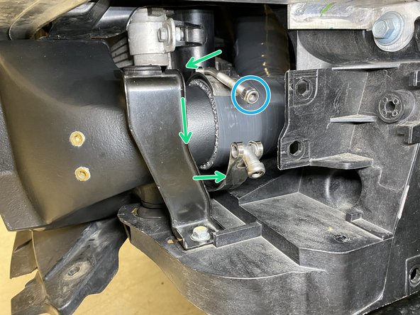
The rubber mounts will fit into the mounting pockets shown with the red arrows
-
-
-
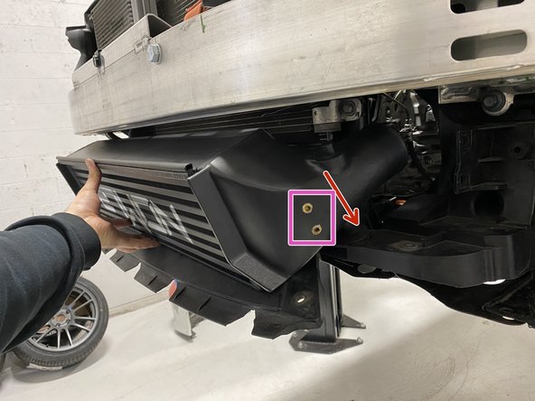
NOTE: the ports in the intercooler were added by 27WON for intercooler testing & validation. This will NOT be present on your purchased intercooler
-
We highly recommend a friend to help support the intercooler in this process, but the instructions are setup so one person can complete the install
-
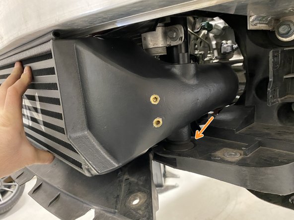
Holding the intercooler at an angle as shown, place the rubber mounts into the pockets
-
Verify the rubber mount is fulled seated in the pocket
-
Place the OEM bracket over the top peg and align for the bolt
-
Install the 10mm bolt. Torque to 10-12 lb-ft
-
-
-
NOTE: the ports in the intercooler were added by 27WON for intercooler testing & validation. This will NOT be present on your purchased intercooler
-
Verify the rubber mount is fulled seated in the pocket
-
Place the OEM bracket over the top peg and align for the bolt
-
Install the 10mm bolt. Torque to 10-12 lb-ft
-
Install the 12mm bolt holding the horn. Torque to 10-12 lb-ft
-
Verify the seal is not completely crushed into the crashbar. It should have a small gap to slight press against the crashbar
-
The intercooler will stay in place with both brackets installed
-
-
-
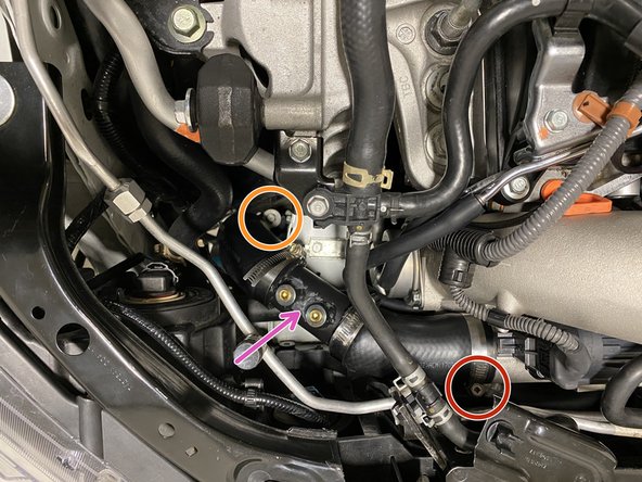
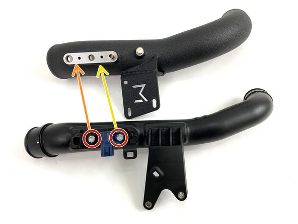
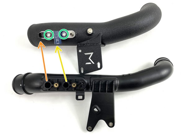
Remove the two (2) bolts holding the sensors using an 8mm socket and ratchet
-
Pull the temperature sensor from the OEM cold pipe and press into the 27WON cold pipe in the port shown
-
Pull the MAP sensor from the OEM cold pipe and press into the 27WON cold pipe in the port shown
-
You can apply a VERY light layer of engine oil on the sensor o-rings to improve install
-
Using an 8mm socket and torque wrench, torque each to 3-5 lb-ft
-
-
-
Place the silicone coupler over the intercooler outlet as shown
-
Silicone orientation should match close to shown, but will be adjusted once the cold pipe is installed
-
Slide the coupler over the intercooler outlet until it stops
-
Silicone coupler may be touching the radiator core support slightly, this is ok
-
-
-
Place a provided 67-75mm T-Bolt clamp onto the throttle body silicone as shown
-
Throttle body side of coupler
-
Cold pipe side of coupler
-
Place the throttle body silicone into the engine bay
-
Slide onto the throttle body
-
Precise fitment and clamping will be completed after the cold pipe is installed
-
-
-
Place a 79-87mm T-Bolt clamp onto the throttle body silicone. Position the nut on the driver side facing up as shown for easy access
-
Place a 79-87mm T-Bolt clamp onto the cold side IC outlet silicone. Position the nut on the rear side facing up as shown for easy access
-
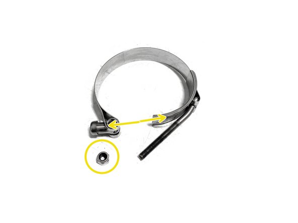
Locate a 67-75mm T-Bolt clamp and remove the nut from the threaded rod
-
Pull the threaded rod out of the coupling so the clamp and expand open as shown
-
Place the 67-75mm T-Bolt clamp around the installed cold side IC outlet silicone as shown
-
Thread the nut back onto the rod so you do not loose it
-
Precise fitment and clamping will be completed after the cold pipe is installed
-
-
-
Place the curved end of the 27WON cold pipe into the open space in the engine bay
-
Rotate the cold pipe so the other end goes under the wiring harness towards the throttle body silicone
-
While holding the throttle body silicone, press the cold pipe into the silicone coupler as shown
-
While holding the cold side IC outlet silicone, press the cold pipe into the silicone coupler as shown
-
Adjust the cold pipe orientation and fitment in the silicone couplers so the holes in the mounting bracket align with the thread holes on the engine
-
-
-
Install the provided M6x1.0x20mm flange bolts through the 27WON cold pipe mounting bracket into the engine
-
Tighten the bolts to snug, but you can still adjust the cold pipe slightly
-
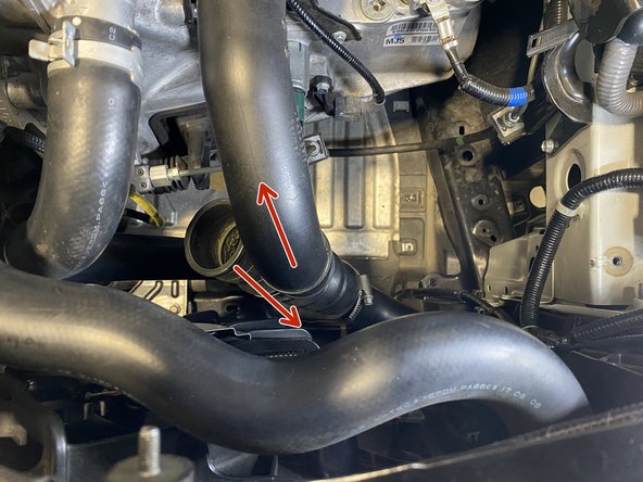
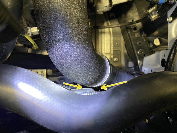
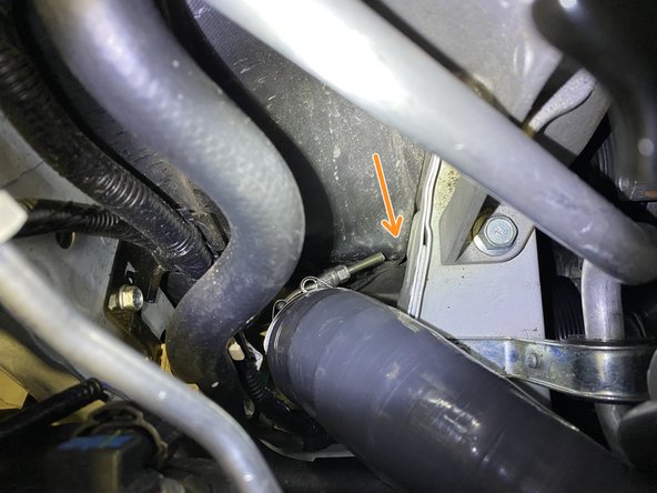
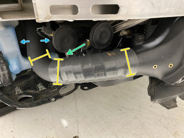
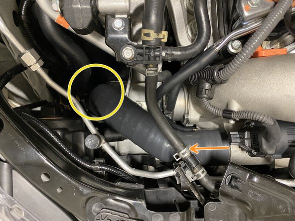
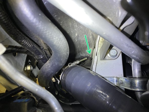
Slide the cold pipe towards the engine until you have a little more than a credit cards worth of gap between the cold pipe and the coolant hosing and hose clamp
-
You do not want the cold pipe touching. Noise and damage will occur
-
Verify there is a small amount of clearance between the cold pipe and fan shroud
-
With cold pipe positioned, torque the two (2) mounting bolts to 7-8 lb-ft
-
-
-
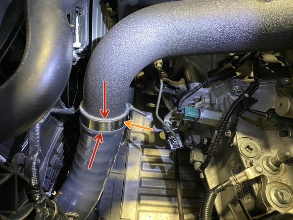
Adjust the silicone position and verify the silicone is fully pressed onto the cold pipe
-
Place the T-Bolt clamp as shown and tighten with a 10mm socket and ratchet until the silicone bulges slightly
-
Remove the nut from the threaded rod
-
Insert the threaded rod back through the clamp coupling
-
Place the T-Bolt clamp as shown and tighten with a 10mm socket and ratchet until the silicone bulges slightly
-
-
-
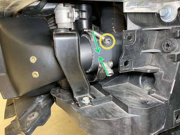
Adjust the silicone position and verify the silicone is fully pressed onto the throttle body
-
Place the T-Bolt clamp as shown and tighten with a 10mm socket and ratchet until the silicone bulges slightly
-
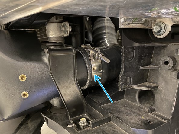
Adjust the silicone position and verify the silicone is fully pressed onto the cold pipe
-
Place the T-Bolt clamp as shown and tighten with a 10mm socket and ratchet until the silicone bulges slightly
-
-
-
Connect the temperature sensor
-
Connect the MAP sensor
-
Press the rubber hose onto the barb fitting and use needle nose pliers to position the spring clamp over the hose where the barb is pressed in
-
Press the green wire loom clip into the square hole in the mounting bracket
-
-
-
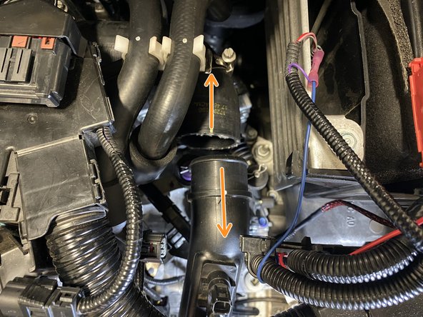
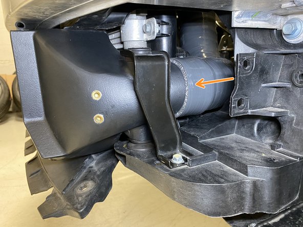
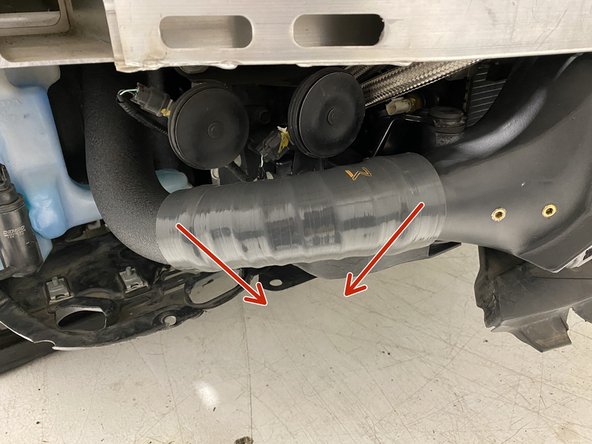
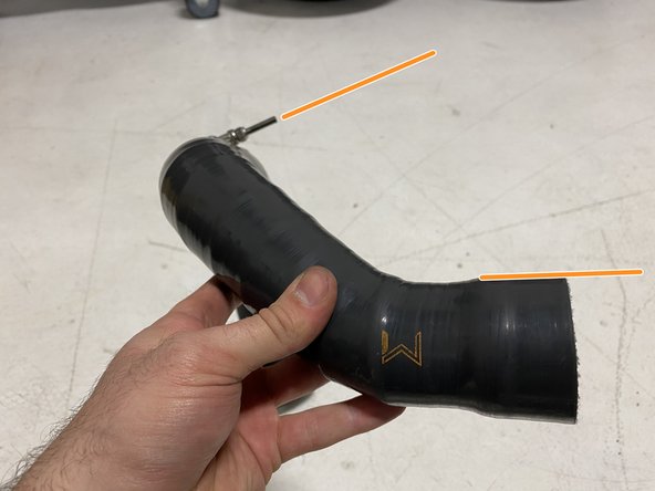
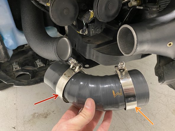
NOTE: Steps 39, 40, & 41 show how to correctly orientate the Hot Side Turbo Outlet Silicone and Hot Side Pipe with the T-Bolt Clamp
-
The reason for this is to make the installation of the T-Bolt clamp at this location much easier by aligning and tighten outside of the car instead in a difficult location in the car
-
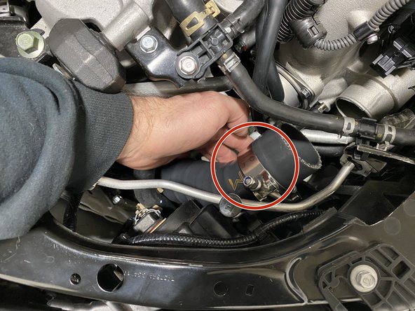
The T-Bolt clamp location will end up here, in a difficult to reach and tighten location
-
The orientation of the T-Bolt clamp is important, if orientated incorrectly the T-Bolt clamp will rub on other components causing noise and damage
-
Please proceed to next step before assembling hot side piping
-
-
-
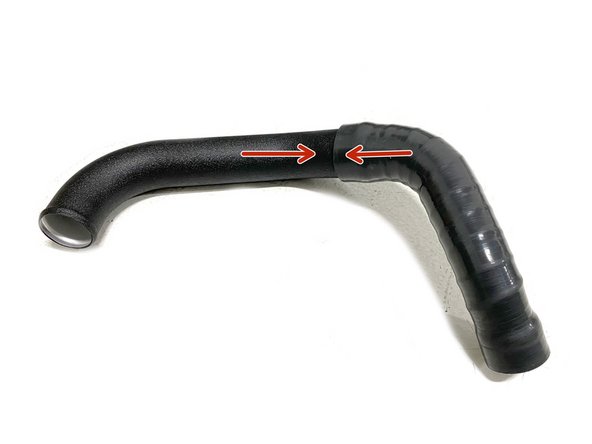
Install the turbo outlet silicone onto the hot side pipe as shown
-
Only one end of the silicone will fit
-
The "more straight" end of the hot side pipe is used
-
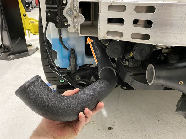
Route the assembled silicone and pipe up through the fender opening that the OEM hot pipe was routed through
-
Press the silicone onto the compressor outlet of the turbo inlet pipe
-
You may notice that the alignment of the hot side pipe is "off". That's fine, it will be corrected in the next step
-
-
-
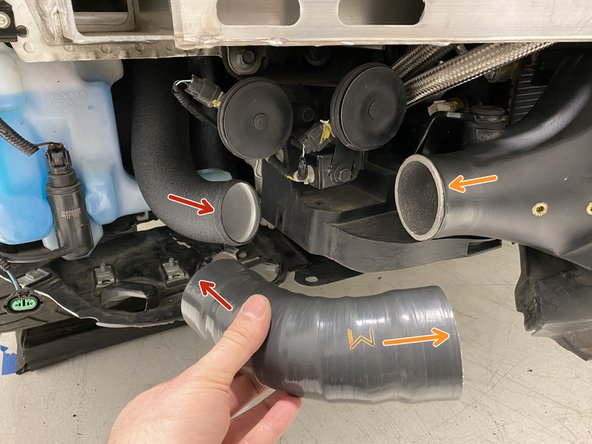
Note the orientation of the W logo, this should match the image. Only one end of the hot side IC inlet silicone will fit onto the intercooler
-
Install the hot side IC inlet silicone onto the hot side pipe
-
Install the hot side IC inlet silicone onto the intercooler
-
Twist the hot side pipe and hot side IC inlet silicone until you find good alignment between both pipe and the intercooler
-
The "designed" position will be come obvious as you start adjusting because the parts will find a spot where they seem to fit correctly
-
Verify there is approximately 3/4 inch of clearance to the horn
-
When the pipe and silicone is positioned correctly, the pipe should be able to move side to side approximately 1/2 inch without contacting other components. This is needed for normal engine movement
-
Verify the turbo outlet silicone is still pressed onto the turbo inlet pipe and the hot side pipe correctly
-
-
-
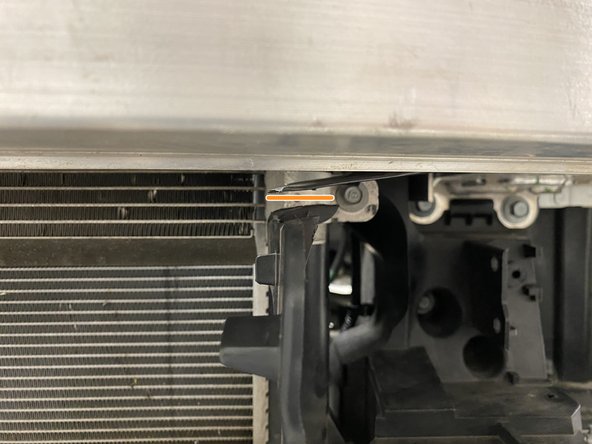
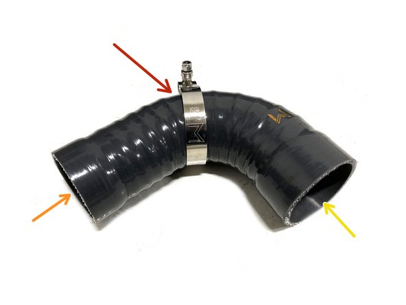
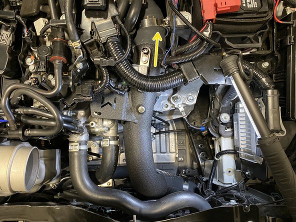
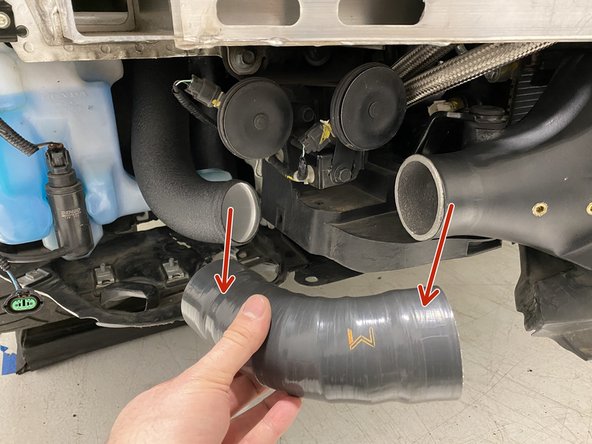
In this process try not to disrupt the assembly between the hot side pipe and turbo outlet silicone. You want to maintain the alignment
-
Remove the hot side IC inlet silicone without disturbing pipe on the left side
-
Pull the turbo outlet silicone off the turbo inlet pipe without disturbing interface in yellow circle
-
Route the assembled hot side pipe and turbo outlet silicone down and out of the vehicle
-
-
-
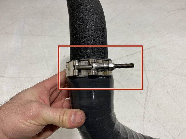
Install a 63-71mm T-Bolt clamp over the pipe to silicone interface as shown
-
Orientate the T-bolt clamp threaded rod angle to approximately match the image shown
-
Tighten the T-bolt clamp with a 10mm socket and ratchet until the silicone bulges slightly
-
-
-
Again, route the assembled silicone and pipe up through the fender opening that the OEM hot pipe was routed through
-
Install a 51-69mm T-Bolt clamp on the turbo outlet silicone as shown
-
Press the silicone onto the turbo inlet pipe as shown
-
Place the T-Bolt clamp as shown and tighten with a 10mm socket and ratchet until the silicone bulges slightly
-
Verify the threaded rod of the T-Bolt clamp installed in the previous step has approximately 1/2 inch clearance to the vehicle chassis
-
Adjusting this T-Bolt while installed in the vehicle is difficult
-
-
-
Place a provided 63-71mm T-Bolt clamp onto the hot side IC inlet silicone as shown
-
Place a provided 67-75mm T-Bolt clamp onto the hot side IC inlet silicone as shown
-
Install hot side IC silicone onto the hot side pipe and intercooler as shown
-
Twist the silicone to get correct fitment
-
Verify there is approximately 3/4 inch of clearance to the horn before the clamp is positioned
-
Place the T-Bolt clamp as shown and tighten with a 10mm socket and ratchet until the silicone bulges slightly
-
-
-
We strongly recommend using a friend to help you with bumper reinstall. This makes it much easier to prevent damage to the paint of the vehicle
-
Lift the bumper close to the front of the vehicle
-
Plug in fog lights on both sides of the car by reaching between the bumper and rest of the vehicle as you did in step 10. The plugs will click audibly when fully plugged in
-
-
-
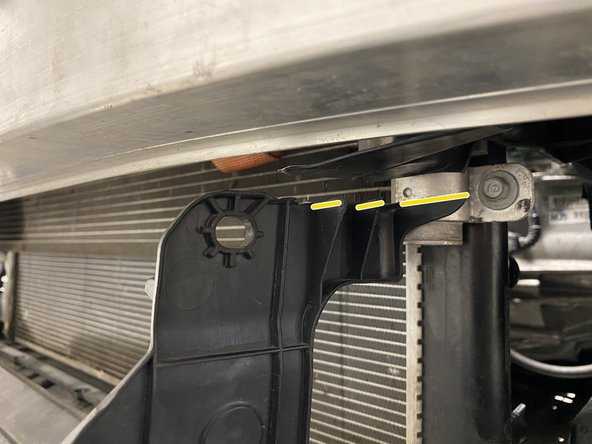
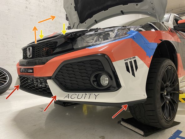
Start by lifting the bottom edge of the bumper into position first
-
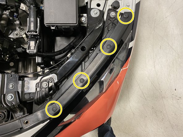
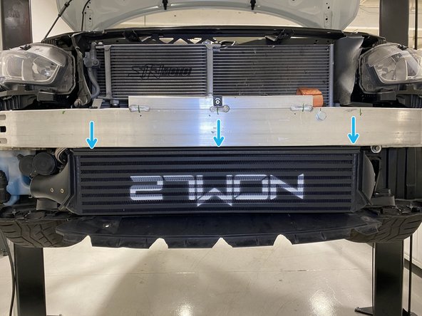
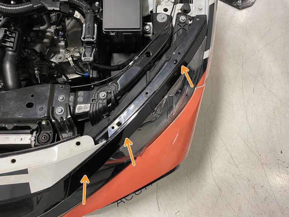
Then lift the top of the bumper upwards and inwards to place it on top of the upper bumper support
-
Upper bumper support labeled with yellow arrows
-
The corners of the bumper can easily get caught during this process. Ensure they do not get caught to prevent damaging your paint
-
Starting on the driver's side, work your way from the inner corner (left in image) of the headlight to the corner of the bumper and connect the five clips removed in steps 8 and 9
-
Repeat for the other side of the vehicle
-
-
-
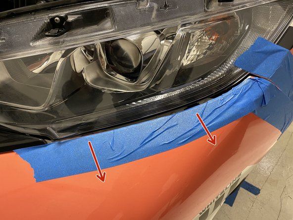
It is common for the fender liner to end up outside of the rear edge of the bumper
-
Push the fender liner so all parts of it end up inside the rear edge of the bumper/front lip
-
You can then press the corner of the bumper into the clip below the marker light
-
Repeat this step on the other side of the vehicle
-
-
-
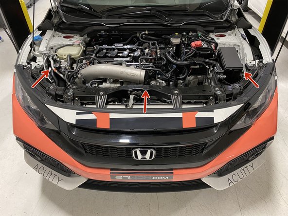
For clarity, the image of the underside of the car was split into two images. Both images show the center push clips
-
From the underside of the front bumper, reinstall:
-
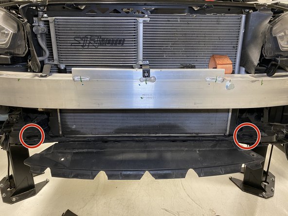
Use 10mm socket & ratchet to install the two (2) bolts shown in red circles
-
Seven large push clips
-
Two 5mm Allen bolts using a 5mm Allen key or socket. Tighten until snug
-
-
-
Secure the bumper to the fender liner using the two (2) OEM Phillips head screws removed in step 4. Tighten until snug using a Phillips screwdriver
-
Position the upper headlight trim just above the headlight and gently push it inward to connect the two clips to the headlight
-
Often these clips will connect themselves when the bumper is reinstalled. If not, there will be an audible click as they are positioned
-
Repeat on the other side of the vehicle
-
-
-
Replace the OEM hood weather stripping on top of the top edge of the bumper and secure with:
-
One medium push clip
-
Three small push clips
-
Repeat on the other side of the vehicle
-
Reinstall the upper radiator panel and secure with 11 push clips removed in step 3
-
-
-
Please reference the installation instructions for the intake system you have installed in your Civic
-
Reinstall your intake system
-
Verify clearance to the 27WON Cold Pipe during your installation
-
Fitment for the 27WON Intercooler & Piping Upgrade has been verified for 27WON intake systems. Call us to verify fitment for OEM and other aftermarket intakes
-
-
-
Check for boost leaks
-
Check for boost leaks at all intercooler and piping connections
-
Once the car is up to temperature (170degF), complete a drive in which you can get the engine into high boost
-
If a whistling sound is heard, you may have a small boost leak, check and tighten the connections for the intercooler and piping
-
Tuning:
-
It is highly recommended to have the vehicle tuning revised and updated for the new intercooler and piping kit although it is not required
-
-
-
This completes the installation of your 27WON Performance L15 Intercooler & Piping Kit
-
We hope you were impressed with your 27WON experience and love your new Intercooler for years to come. Email us at sales@27won.com or call us at 571-271-0271 with any questions or concerns
-
Please Leave a review here: https://store.27won.com/2016-civic-inter...
-
Stay Connected with the latest developments with the 27WON Monthly Newsletter: https://store.27won.com/27won-newsletter...
-
See the latest Products and Tech Videos from 27WON with a quick Subscribe: https://www.youtube.com/channel/UCF7uI0N...
-
Share your experience using #27WON on Instagram and Facebook
-