Introduction
In this installation guide we have provided step by step instructions to setup, remove the OEM exhaust, and install the 27WON Performance Exhaust.
Advisory:
- Working under the vehicle requires a safe and sturdy location for the vehicle to sit on jackstands
- Use the hydraulic jack to raise the vehicle and the jack stands to support the vehicle in the OE recommended locations
- The exhaust piping will be hot after recent vehicle operation. Allow the vehicle to cool or use a fan to cool the exhaust piping before working on the vehicle
Tools
-
-
First and foremost; THANK YOU for becoming a part of the 27WON Family. We hope to REDEFINE your experience of the aftermarket with the highest level Parts, Customer Service, Packaging, & Support.
-
An exhaust silencer can help reduce NVH caused by exhaust resonance. For instructions to install an exhaust silencer go here: FK8-6-101-10/11 Silencer Installation
-
As of 2026 an optional exhaust silencer is included with 27WON FK8 Exhaust Systems
-
-
-
The following instructions are shown with no bubble wrap or cardboard for clarity of the installation process
-
We recommend leaving as much protective bubble wrap/cardboard on the exhaust as possible during install to protect against scratches and dings during the process
-
Cut holes in the bubble wrap to expose on the flanges, hanger rods, and fastening locations
-
-
-
The 27WON packaging is not only designed to get your performance parts to your doorstep safely, but to also provide you with an awesome garage banner and/or comfy cardboard mat to lay on under your car for installation
-
You can cut out the banner as shown with the orange square
-
Or you can use the entire unfolded box as a mat to lay under your vehicle
-
Remove the staples from the box as they don't feel great on your backside...
-
-
-
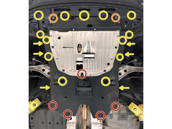
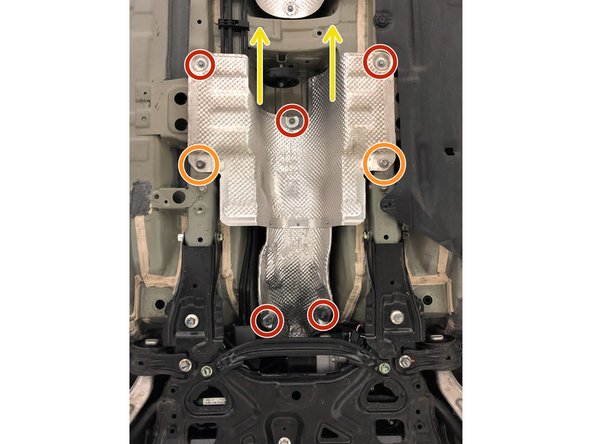
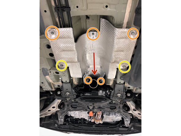
Locate the engine undertray to gain access to the connections of front-pipe
-
Take pictures or take a good look at how the under tray fits with the other under body shields to help with easier reinstallation
-
Use a 10mm socket & ratchet to remove the five 10mm bolts (red circles)
-
Use a 5mm Allen Key/Allen Socket to remove the two (2) Allen head bolts (orange circles)
-
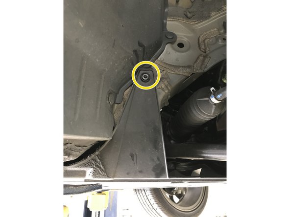
Use a Flathead screwdriver or push clip removal tool to remove the 19 push clips from the under tray (yellow circles and arrows)
-
For clarity on the push clips on the sides of the under tray (labeled with the arrows) please proceed to the next step
-
-
-
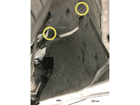
The images in this step show the push clips on the side of the under tray. These are labeled with the arrows in the previous step
-
Passenger side shown, please repeat for the driver side before removing the under tray
-
Remove the engine under tray from the vehicle
-
-
-
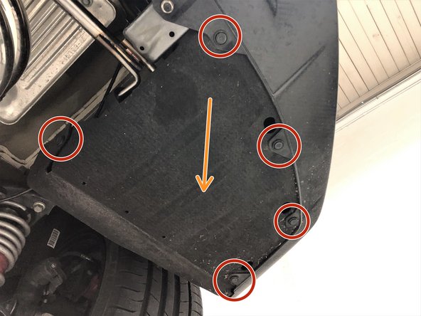
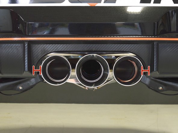
At the rear passenger side of the vehicle, remove the five push clips that hold the rear bumper fender liner to the rear bumper
-
Pull the rear bumper fender liner downward to gain access to the rearmost exhaust hangers
-
Repeat these steps on the other side of the vehicle
-
-
-
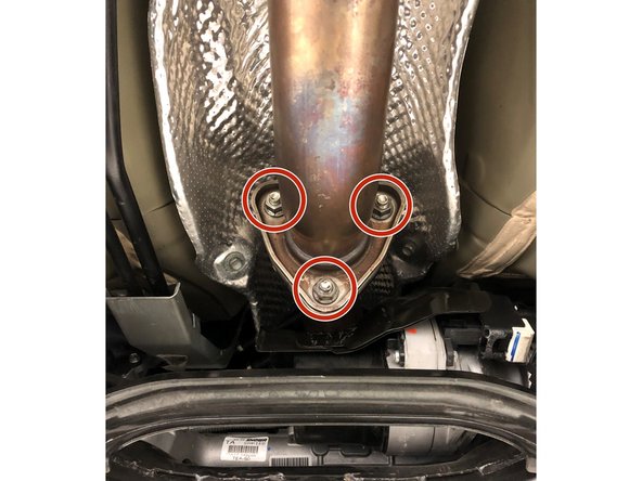
Verify that the exhaust is not to hot to touch, if still hot use a fan to cool the exhaust piping before proceeding
-
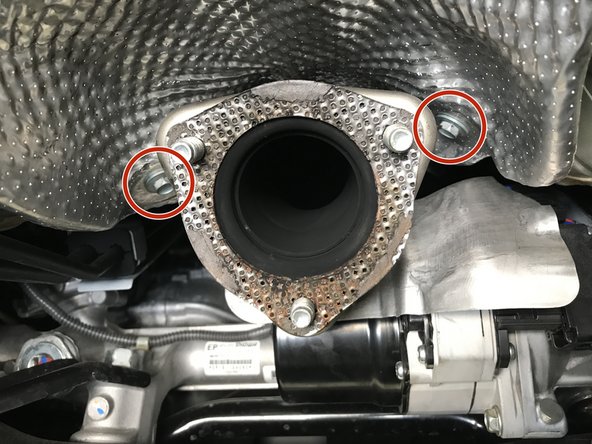
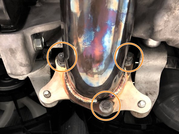
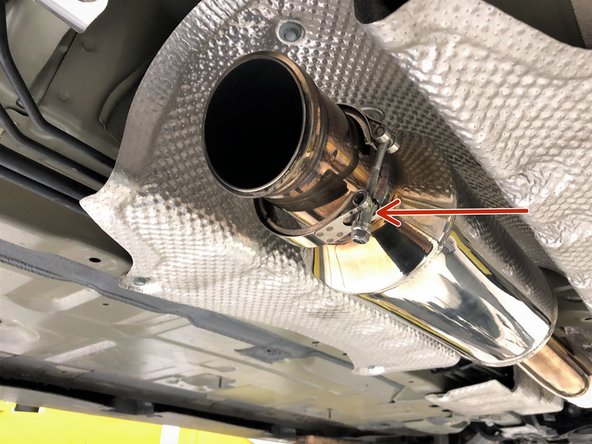
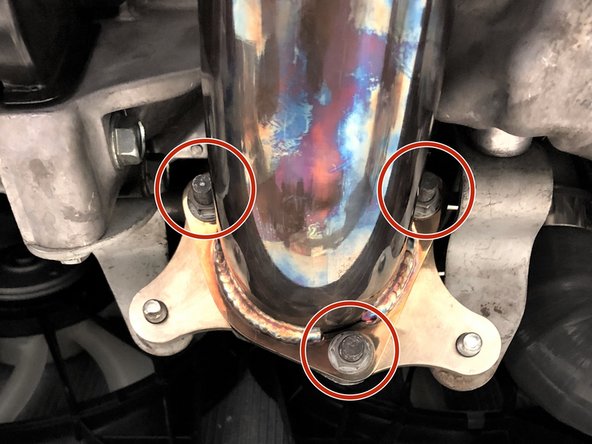
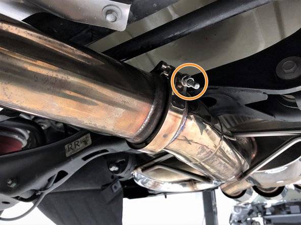
Locate the connection between the front-pipe and down stream exhaust
-
Use 14mm socket & ratchet to remove 3 OE nuts
-
-
-
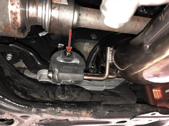
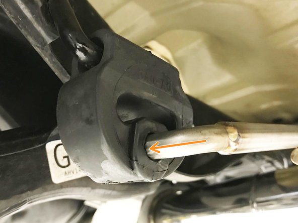
This step and the next are meant to show you how to remove a rubber hanger - Parts are not being removed from the vehicle at this time
-
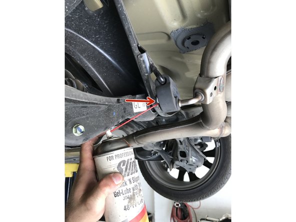
Exhaust hangers can be difficult to remove without lubricant
-
Apply small amount of silicone spray lubricant to end of hanger rod
-
-
-
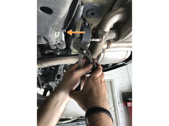
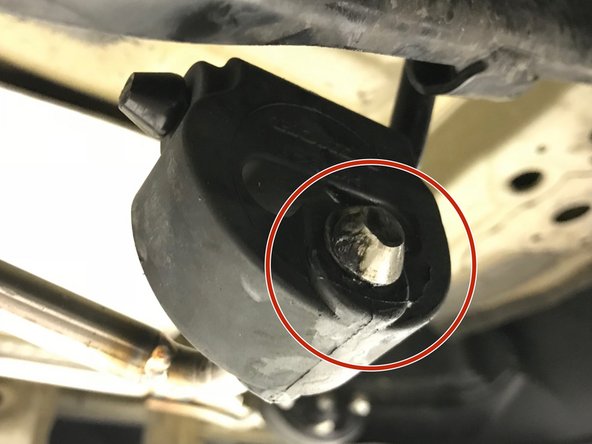
Use tongue & groove pliers to press the rod out of the rubber hanger
-
Hook the lower jaw to the edge of the rubber hanger. Hook the end of the upper jaw on the end of the rod to push the rod out of the hanger
-
-
-
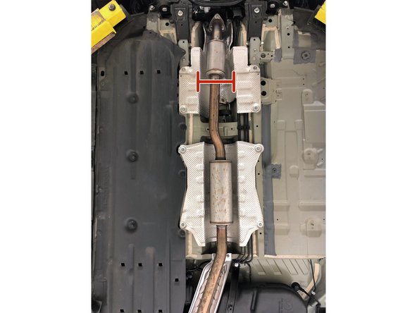
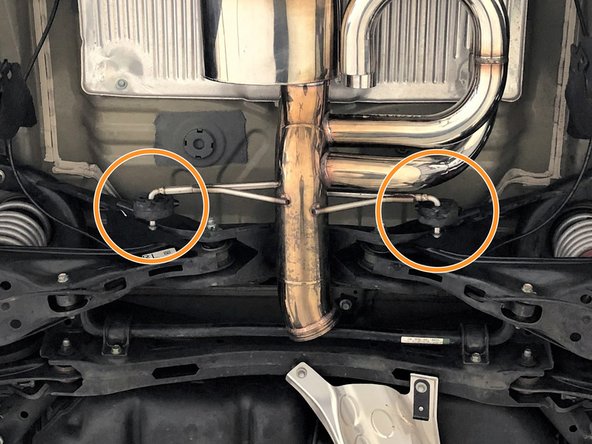
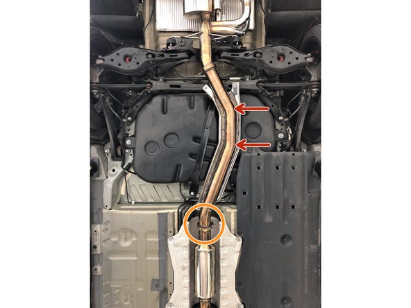
Support the exhaust mid-section with a jack stand, bungee cord, or second set of hands before the next step
-
Support Mid-Section in between the resonators as shown
-
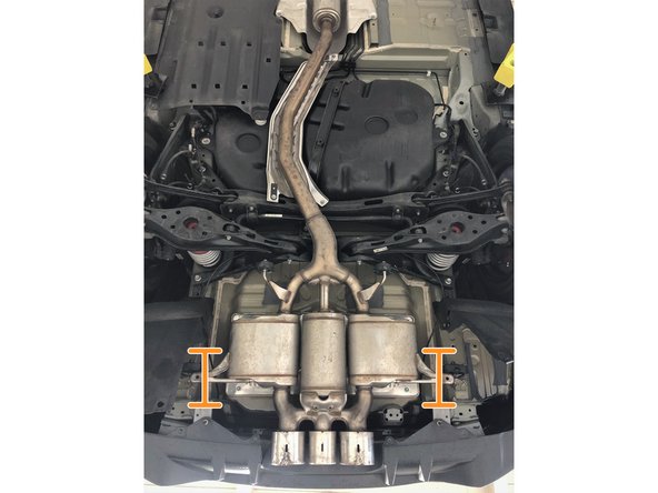
Support Rear Muffler Section in two locations as shown
-
-
-
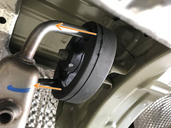
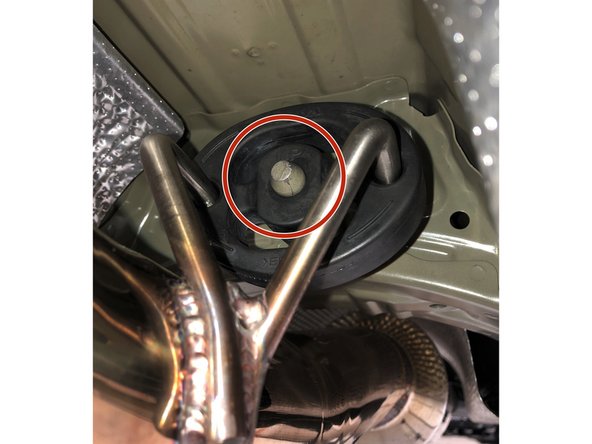
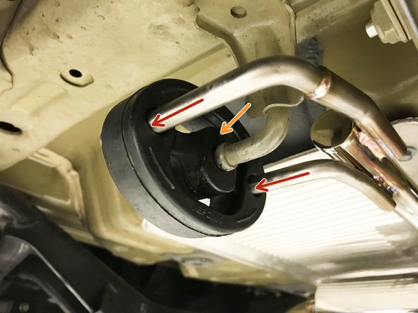
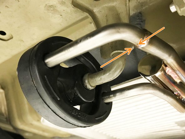
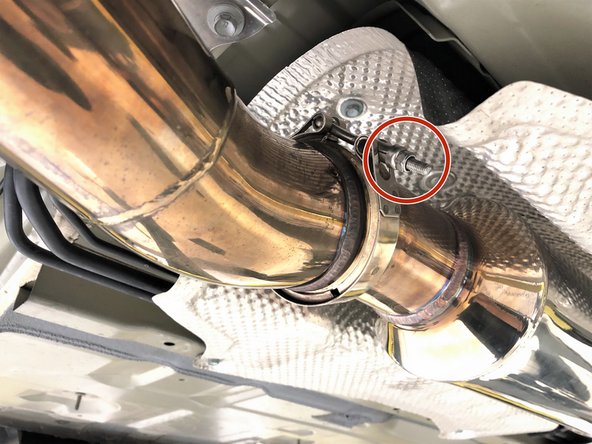
Locate the dual rod rubber hanger in the exhaust mid section
-
Use the tongue & groove pliers to pull the rubber hanger off the chassis rod in the direction of the red arrows
-
The rubber hanger will come off with the OE exhaust
-
-
-
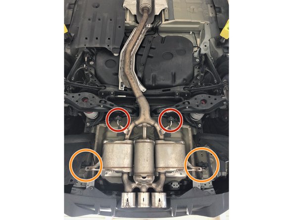
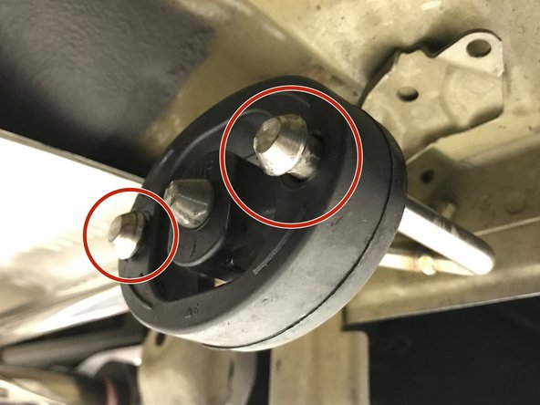
Forward single rod rubber hangers
-
Rearward dual rod rubber hangers
-
-
-
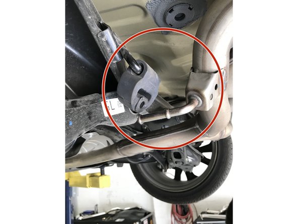
Pull the single rod hanger completely off the hanger rod and pivot out of the way as shown
-
Complete for both passenger and driver sides
-
-
-
Pull the dual rod rubber hangers off the exhaust hanger rods; the rubber hangers will stay on the vehicle
-
Lower the exhaust to the ground and remove from under vehicle. A second set of hands can be helpful here as the OE exhaust is heavy
-
-
-
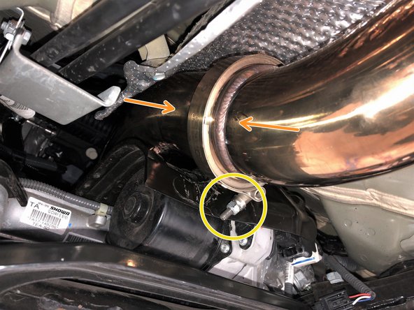
Use a 10mm socket and ratchet to remove the five 10mm bolts holding the heat shield
-
Two of the 10mm bolts are slightly obstructed by the front-pipe as shown
-
Front-pipe has been removed for clarity of image, but does not need to be removed to relocate the heat shield out of the way
-
Use a 14mm socket and ratchet to remove the two 14mm bolts holding the heat shield
-
Pull the heat shield rearward, and remove it from the vehicle
-
-
-
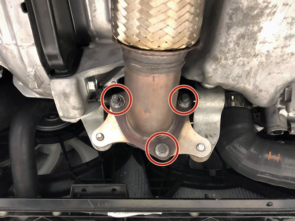
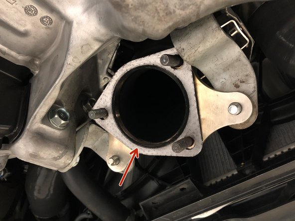
Use a 14mm socket and ratchet to remove the three OE nuts that connect the OE front-pipe to the downpipe
-
It is possible that the studs will thread out of the downpipe flange. This is not an issue, the stud can be threaded back into the flange like a bolt when installing the new front-pipe
-
-
-
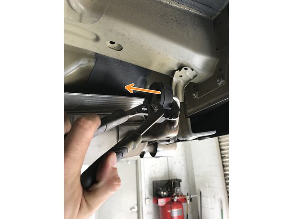
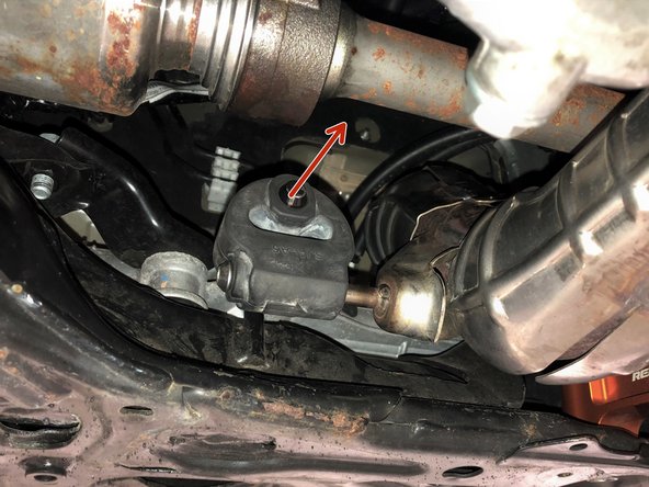
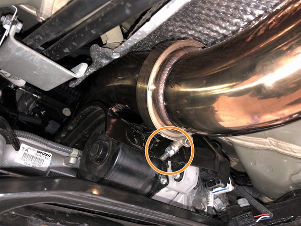
Pull the rubber hanger on the OE front-pipe free from the hanger rod on the chassis in the direction shown
-
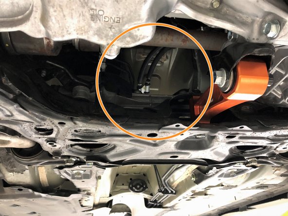
Remove the OE front-pipe from the vehicle through the access point directly under the engine
-
-
-
Locate and install the provided 80mm "2 & 1" gasket onto the downpipe studs
-
Please note, a prototype gasket is shown, your gasket will differ slightly in appearance
-
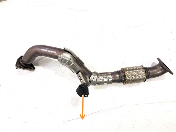
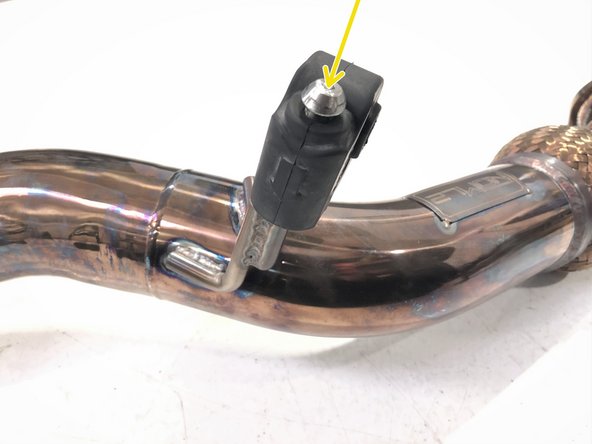
Remove the OE rubber hanger from the OE front-pipe
-
Install the OE rubber hanger onto the 27WON front-pipe
-
There is an arrow on the rubber hanger that shows the correct direction to install the hanger
-
-
-
Install the 27WON front-pipe through the access point used earlier to remove the OE front-pipe
-
Reinstall the OE rubber hanger onto the hanger rod as shown
-
Thread on the three OE 14mm nuts by hand. Leave loose for now for ease of installation of the remaining exhaust components
-
-
-
Reposition the front-pipe heat shield by sliding the front edge above the 27WON front-pipe as shown
-
Use a 10mm socket and ratchet to reinstall the five 10mm bolts removed from the heat shield in step 15. Tighten to 6-8 lb-ft
-
Use a 14mm socket and ratchet to reinstall the two 14mm bolts removed from the heat shield in step 15. Tighten to 8-10 lb-ft
-
-
-
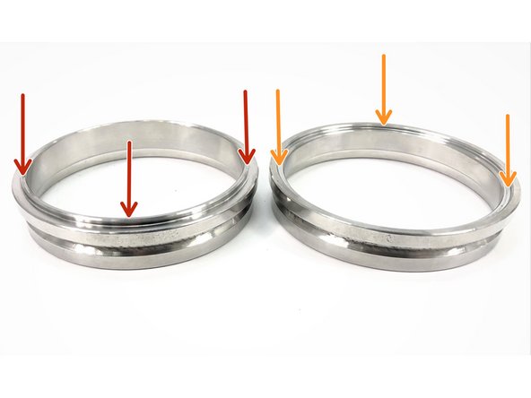
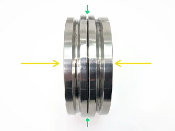
The 27WON FK8 exhaust uses v-band joints between the different pipe sections
-
Each joint will have a "male" side and a "female" side
-
The male side has a small lip
-
The female side has a small recess
-
The male side fits into the female side to align the pipe sections. The clamp squeezes the two sides together to provide the seal
-
When connecting two pipe sections, ensure the flanges are properly seated and aligned as shown in the second image. Failure to do so will result in exhaust leaks
-
A small gap between the flanges shown with the green arrow is normal
-
-
-
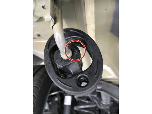
Before continuing the installation of 27WON Performance Exhaust please identify the required orientation of the rubber exhaust hangers
-
Each dual rod rubber hanger has "UP" formed in the mold on the center part of the rubber hanger. Verify that the "UP" on the rubber hanger is up before installing the 27WON exhaust
-
-
-
Expose the hanger rods through the bubble wrap, but maintain bubble wrap protection on remaining exhaust
-
Install the OE dual rod rubber exhaust hanger onto the hangers of the 27WON forward mid-section
-
Use of silicone spray may be needed
-
Ensure the rubber hanger is facing the correct way up as shown
-
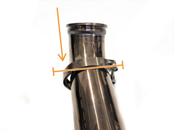
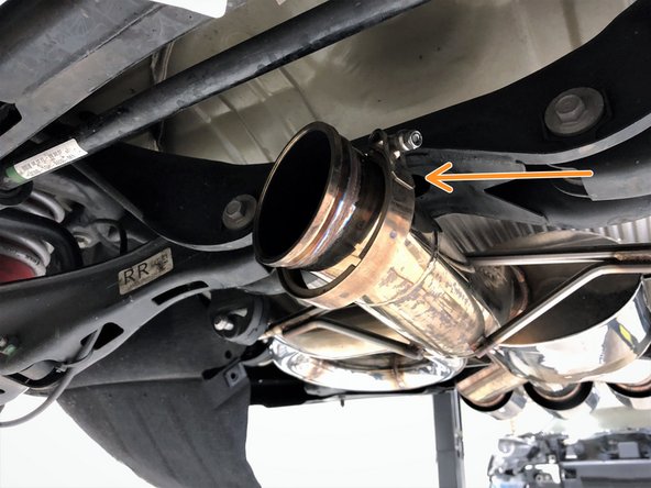
Slide one of the supplied v-band clamps over the end of the 27WON forward mid-section marked with the orange arrow
-
The clamp orientation shown is easy to access once installed on the vehicle
-
-
-
Silicone spray may help installation on the chassis hanger rod
-
Install the forward mid-section onto the vehicle. Mount the rubber hanger on the chassis hanger rod. Verify the rod bead is fully through the rubber hanger
-
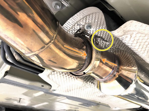
Following the v-band guidelines in step 21, loosely attach the forward mid-section to the front-pipe using the v-band clamp as shown
-
Tighten the clamp using a 10mm socket and ratchet only until the clamp holds the front-pipe to the forward mid-section
-
Leaving the clamp loose for now allows the forward mid-section to rotate to allow for easier alignment of the remaining sections
-
-
-
Locate QTY=2 sets of 20mm length M10 bolts
-
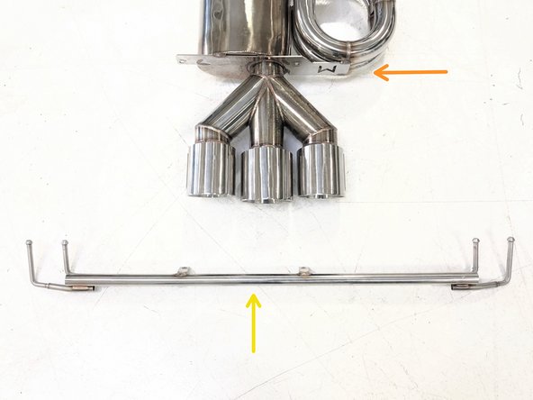
Locate the muffler section
-
Locate hanger bar
-
-
-
Expose the hanger rods and bolting locations through the bubble wrap, but maintain bubble wrap and cardboard protection on remaining exhaust
-
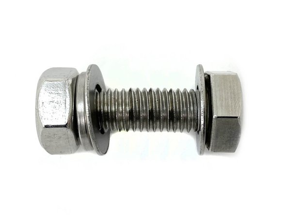
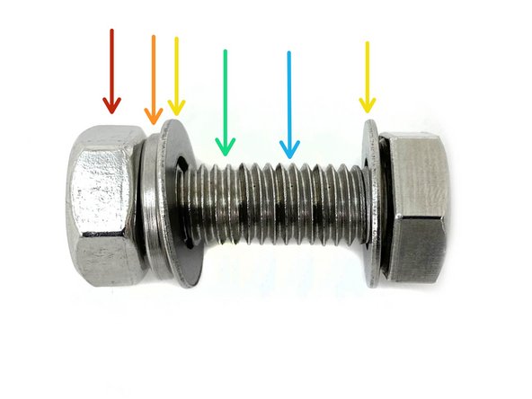
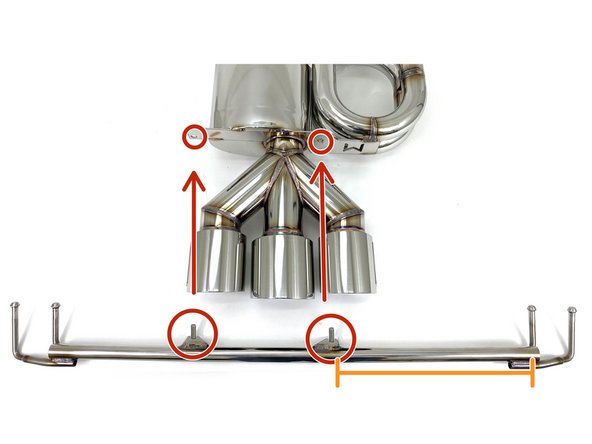
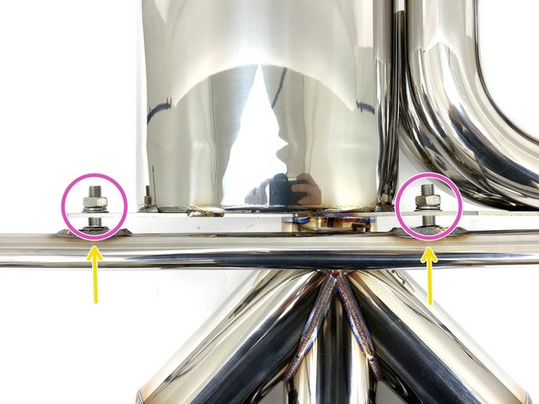
Hardware setup shown in first image. This setup must be followed to ensure proper fastening.
-
17mm Hex Nut
-
M10 Lock Washer
-
M10 Flat Washer
-
Muffler Mounting Location
-
Hanger Bar Mounting Location
-
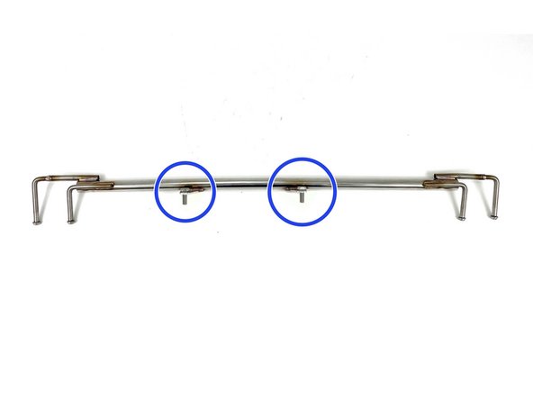
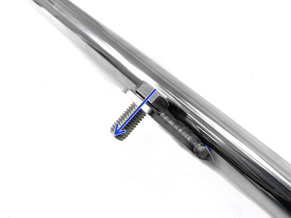
Install the M10x20mm bolt with flat washer through the hanger bar.
-
-
-
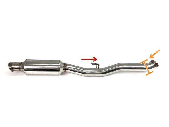
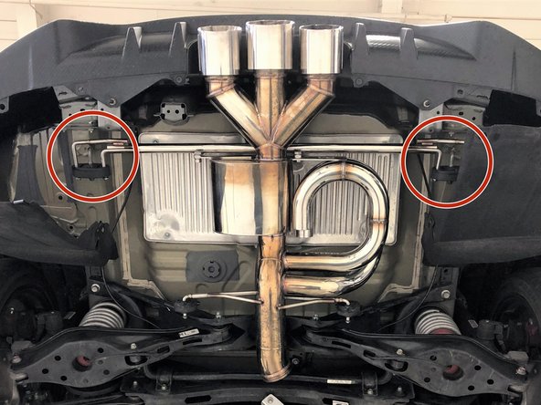
The two brackets on the hanger bar circled in red will align with the holes in plate on the muffler section also circled in red
-
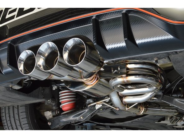
The longer side of the hanger bar (shown with orange mark) will attach on the same side as the side branch resonators (yellow arrow)
-
Align the bar onto the muffler section in the orientation shown and install the remaining hardware onto the M10 bolts
-
Use a 17mm socket and torque wrench to torque the bolts to 30-40 lb-ft
-
-
-
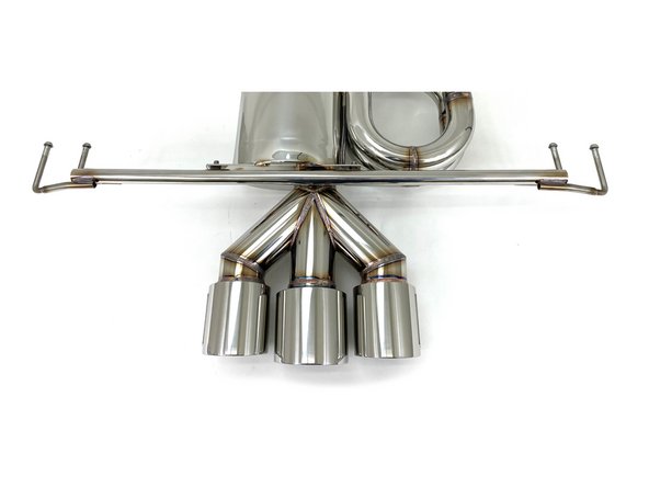
Image shows the muffler section installed for improved clarity in Step 29 & 30
-
An extra set of hands may be useful for the next few steps. Also the use of silicone spray on the hangers may be helpful with installation
-
The hanger bar is located on the top of the 27WON exhaust
-
-
-
While supporting the rear of the muffler section, insert both forward hangers as shown
-
-
-
Then raise the rear end of the muffler section up and insert both rearward hangers
-
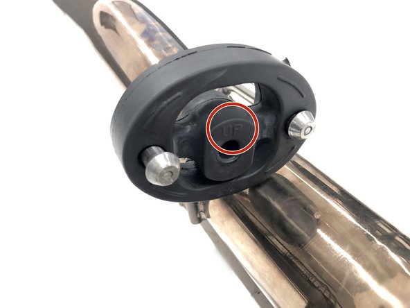
Verify that "UP" is up on the OE dual rod rubber hanger
-
-
-
Verify that the bead of the hanger rod is through both forward rubber hangers as shown
-
-
-
Verify that the bead of the hanger rods are through the dual rod rubber hangers as shown
-
-
-
Verify that the hanger bar is not contacting the chassis. Move the muffler section rearward if the hanger bar is very close or touching the chassis
-
-
-
Slide one of the supplied v-band clamps over the end of the 27WON forward mid-section in the approximate orientation shown
-
Slide one of the supplied v-band clamps over the end of the 27WON muffler section in the approximate orientation shown
-
-
-
An extra set of hands is very useful for this and the next step
-
Lift the 27WON rear-midpipe into position, following the orientation shown
-
Following the v-band guidelines in step 21, loosely attach the rear mid-section to the forward mid-section using the v-band clamp as shown
-
Tighten the clamp using a 10mm socket and ratchet only until the clamp holds the rear mid-section to the forward mid-section
-
Leaving the clamp loose for now allows the rear mid-section to rotate to allow for easier alignment of the remaining joint
-
-
-
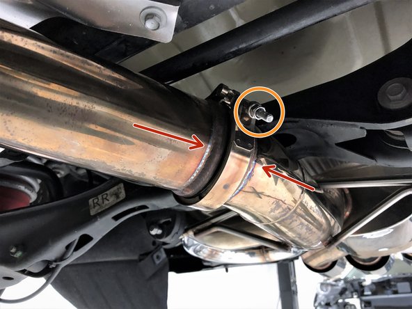
Following the v-band guidelines in step 21, loosely attach the rear mid-section to the muffler section using the v-band clamp as shown
-
Tighten the clamp using a 10mm socket and ratchet only until the clamp holds the rear mid-section to the forward mid-section
-
Leaving the clamp loose for now allows the rear mid-section to rotate to allow for easier final alignment of the exhaust
-
-
-
Starting at the front of the vehicle, double check that no exhaust components are hitting the vehicle
-
If added clearance is needed, the mid-sections are free to rotate and the muffler section can be shifted on its four hangers
-
The hanger on the forward mid-section should sit approximately horizontal for best fit
-
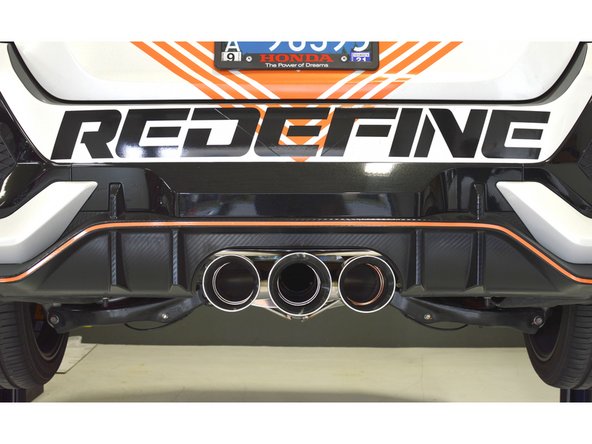
Check exhaust tip alignment in the bumper cutout is centered
-
If misaligned you may need to adjust the hangers supporting the muffler section by moving the hanger rod in the rubber hanger slightly
-
-
-
Once happy with fitment, begin by tightening the three 14mm nuts that attach the front-pipe to the downpipe. Torque to 30-40 lb-ft
-
Next tighten the front-pipe to forward mid-section v-band clamp using a 10mm socket and ratchet. Torque to 8-12 lb-ft
-
Do not over-tighten the v-band clamp as you can damage the clamp and/or joint
-
-
-
Next tighten the forward mid-section to rear mid-section v-band clamp using a 10mm socket and ratchet. Torque to 8-12 lb-ft
-
Finally, tighten the rear mid-section to muffler section v-band clamp using a 10mm socket and ratchet. Torque to 8-12 lb-ft
-
Do not over-tighten the v-band clamps as you can damage the clamps and/or joints
-
Verify exhaust routing clearance and tip alignment again
-
-
-
Remove the protective bubble wrap and cardboard from the 27WON exhaust system as shown
-
Start the vehicle to check for leaks or rattles. If you do find a leak or rattle, please inspect the exhaust further
-
A leak could be caused by a loose v-band clamp, improperly aligned connection, or if debris is stuck between the v-band flanges
-
A rattle could be caused by misaligned pipe or a rubber hanger being orientated incorrectly
-
If you have done these checks and are still having problems then give us a call and we would be happy to help resolve the issue with you
-
-
-
Lift the under tray into position
-
Reinstall the five 10mm bolts with a 10mm socket & torque wrench. Torque to 6-8 lb-ft
-
Reinstall the two 5mm socket flange bolts with the 5mm Allen key & torque wrench. Torque to 6-8 lb-ft
-
Reinstall the 19 push clips at the bottom of the undertray and the sides
-
For clarity on the push clips on the sides of the under tray (labeled with the arrows) please see the next step
-
-
-
The images in this step show the push clips on the side of the under tray. These are labeled with the arrows in the previous step
-
-
-
Stand back from the car and verify that the tips are centered and have sufficient clearance from the bumper
-
If the tips are not centered try gently shaking the exhaust to settle the rubber hangers
-
If the tips are sitting high, there may be a rubber hanger that is upside-down. Verify that all hangers are orientated correctly
-
-
-
Exhaust may smoke for the first 30 minutes or so of use. This is normal
-
Exhaust sound will settle a bit during the first 100 miles of use. This is normal
-
Your Honda has a cold start system which causes louder exhaust for around 15 seconds when you start your car cold
-
Due to driving and first install, the exhaust may shift slightly, be sure to check exhaust routing and tip alignment again after a few hundred miles
-
-
-
This completes the installation of your 27WON Performance Exhaust
-
We hope you were impressed with your 27WON experience and love your new exhaust for years to come. Email us at sales@27won.com or call us at 571-271-0271 with any questions or concerns
-
Please Leave a review here: https://store.27won.com/civic-type-r-cat...
-
Share your experience using #27WON on Instagram and Facebook
-