Introduction
In this installation guide we have provided step by step instructions to install the 27WON Performance Master Cylinder Brake Brace onto the 27WON Front Strut Tower Bar.
Advisory:
- The engine bay will be hot after recent vehicle operation. Allow the vehicle to cool or use a fan to cool the engine bay before working on the vehicle.
-
-
First and foremost; THANK YOU for becoming a part of the 27WON Family. We hope to REDEFINE your experience of the aftermarket with the highest level Parts, Customer Service, Packaging, & Support
-
These instructions were written with a 2018 Civic Type R and 2018 Honda Civic SI. Other models will be similar
-
These instructions are for 10th Generation Honda Civic. For 2022+ use these instructions
-
-
-
Please note that this is an upgrade for the 27WON FSTB only. 27WON FSTB must be installed prior to starting this install.
-
If you need the 27WON FSTB instructions click here: https://www.performanceinstalls.com/Guid...
-
If you don't have a 27WON FSTB yet then you can purchase one here: https://store.27won.com/civic-10thgen-fr...
-
-
-
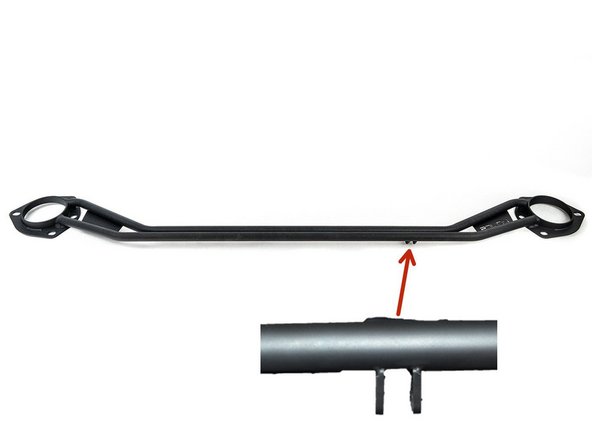
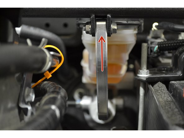
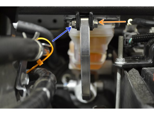
The red arrow shows where the brake brace mounting tabs are located on the front strut tower bar (FSTB)
-
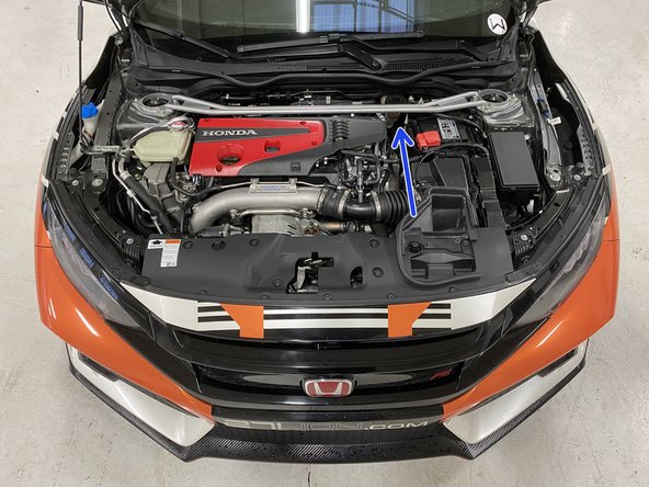
The blue arrow shows where the mounting tabs are located with the FSTB installed on the car, it will be on the side closest to the battery
-
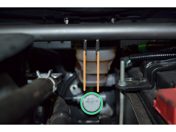
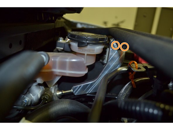
The orange lines show that the mounting tabs will be in line with the master brake cylinder
-
The green circle shows the surface on the master brake cylinder where the brake brace foot will rest
-
Silver color FSTB is used only for install instruction, actual color will vary
-
-
-
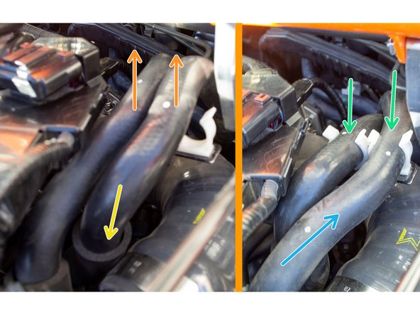
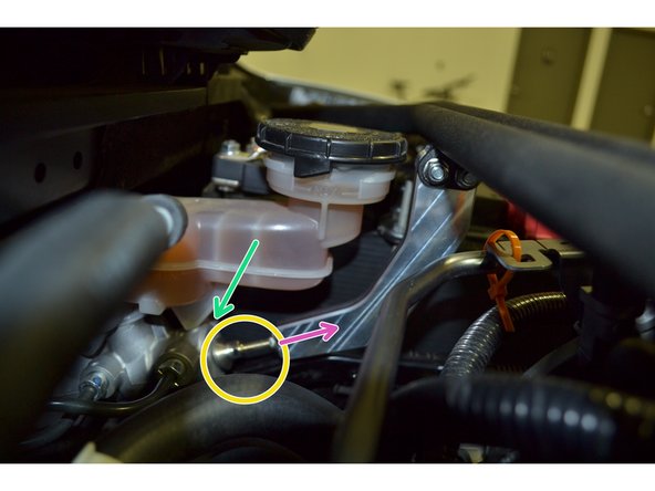
Civic Type-R owners should skip to the next step.
-
Failure to move coolant lines could result in coolant leak due to damaged lines
-
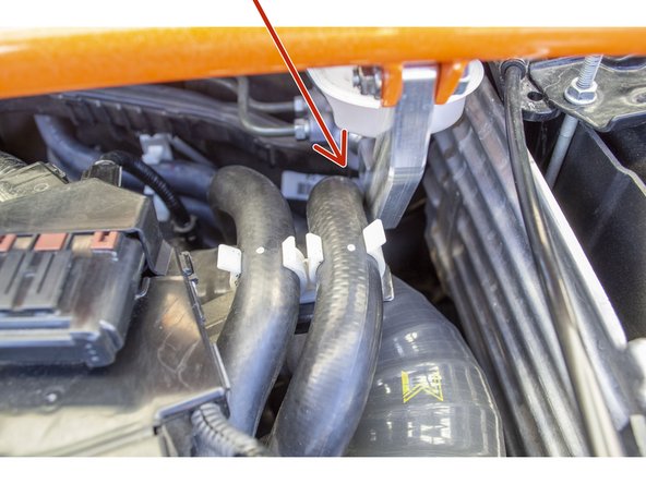
The red arrow shows where the contact will occur if this step is not followed
-
Unclip both coolant lines
-
Notice that the left coolant line is farther forward than the right coolant line
-
Move the left coolant line so that it crosses over the right coolant line as shown
-
Clip the left coolant line into the right clip and the right coolant line into the left clip
-
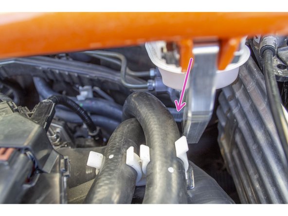
When these steps are done correctly, the brake brace will have plenty of clearance as shown by the pink arrow
-
-
-
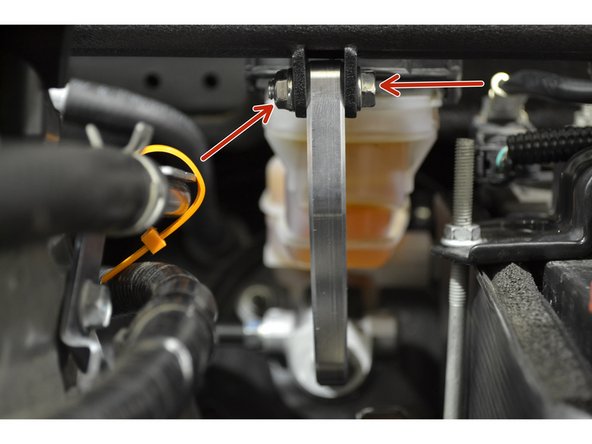
Please note the brake brace shown is a prototype brake brace, actual brake brace shape will vary depending on vehicle model.
-
Insert the brake brace into the tabs and align the holes in the brake brace with the holes in the mounting tabs
-
Insert the two M6 x 1mm x 25mm bolts through the holes in the mounting tabs as shown
-
Loosely thread the two M6 nuts onto the bolts to hold the brace in place
-
-
-
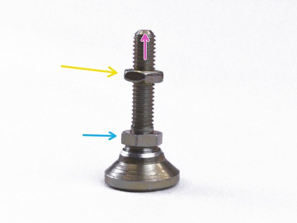
With the brake brace loosely installed check the fitment of the brake brace foot to determine how much adjustment is needed.
-
To adjust the brake brace foot, circled in yellow, thread the top nut, shown by the yellow arrow, toward the bottom of the foot with a 10mm open end wrench
-
The brake brace foot can now be adjusted in or out by turning bottom nut, shown by the blue arrow, with a 10mm open end wrench
-
Once you have adjusted the brake brace foot to the proper location, then with a 10mm open end wrench, thread the top nut towards the brake brace until the nut butts up against the brake brace
-
-
-
With the brake brace foot adjusted, tighten the M6 bolts and nuts installed earlier using either two 10mm wrenches or one 10mm wrench and a 10mm socket with a ratchet, tighten until snug (24-48 in-lbs)
-
-
-
This completes the installation of your 27WON Performance Master Cylinder Brake Brace
-
We hope you were impressed with your 27WON experience and love your new Master Cylinder Brake Brace for years to come. Email us at sales@27won.com or call us at 571-271-0271 with any questions or concerns
-
Please Leave a review here: https://store.27won.com/fstb-master-cyli...
-
Stay Connected with the latest developments with the 27WON Monthly Newsletter: https://store.27won.com/27won-newsletter...
-
See the latest Products and Tech Videos from 27WON with a quick Subscribe: https://www.youtube.com/channel/UCF7uI0N...
-
Share your experience using #27WON on Instagram and Facebook
-