Introduction
In this installation guide we have provided step by step instructions to remove the OEM turbo and install the 27WON GIN turbo on a 2022 Civic EX. Other 2022+ Civic and Integra 1.5T models will be similar
- Working under the vehicle requires a safe and sturdy location for the vehicle to sit on jackstands.
- The exhaust piping, turbocharger, and cooling system will be hot after recent vehicle operation. Allow the vehicle to cool or use a fan to cool the exhaust components before working on the vehicle.
Tools
- Torque Wrench (3/8" Drive)
- Breaker Bar (3/8" Drive)
- 1/4" Ratchet
- 3/8" Ratchet
- 4" Extension (1/4" Drive)
- 3" Extension (1/4" Drive)
- 22mm Oxygen Sensor Socket
- 17mm Socket - Shallow
- 14mm Socket
- 13mm Socket
- 12mm Socket
- 10mm Socket
- 8mm Socket
- 5.5mm Socket
- T30 Torx Socket
- T20 Torx Socket
- 14mm Wrench
- 13mm Wrench
- 12mm Wrench
- 8mm Wrench
- Phillips Screwdriver
- Flathead Screwdriver
- Pliers - Large
- Optional: Push Clip Removal Tool
- Optional: Hose Pliers
- Jack Stand × 2
- Dremel w/Cutting Disc
- PB Blaster
- 1gal - Honda Genuine Coolant
-
-
First and foremost; THANK YOU for becoming a part of the 27WON Family. We hope to REDEFINE your experience of the aftermarket with the highest level Parts, Customer Service, Packaging, & Support
-
-
-
You will proceed to remove the OEM Turbocharger from the vehicle in the coming steps
-
The next steps will be performed underneath the vehicle. Please make sure vehicle is secured on a lift or jack stands
-
-
-
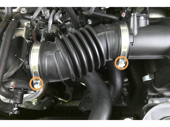
Use a 5.5mm socket and 1/4" ratchet to remove the two (2) clamps (red markups) securing the accordion style intake air tube
-
Remove intake air tube from car and set aside
-
-
-
Remove two (2) screws from Turbo Inlet Pipe (TIP) EVAP valve with T30 Torx Bit
-
Pop both EVAP lines from clip
-
Tuck EVAP valve out of the way as shown (blue box)
-
-
-
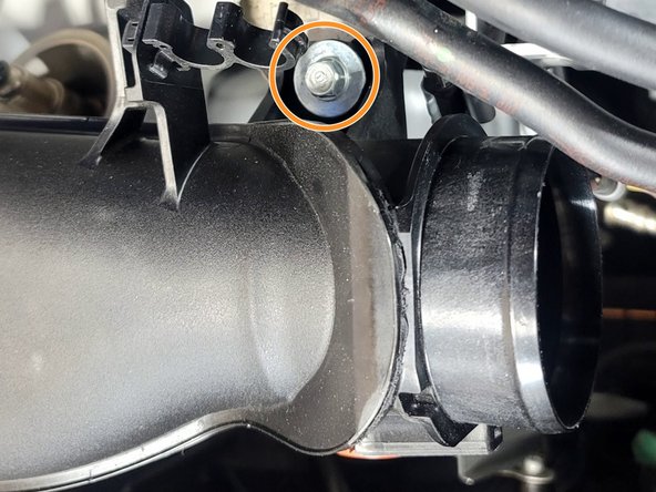
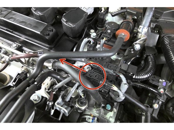
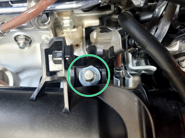
Use 10mm socket and ratchet to remove bolt from TIP bracket near inlet
-
-
-
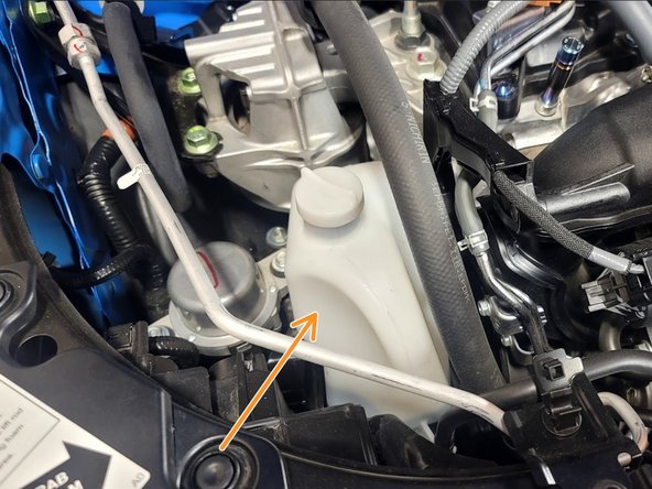
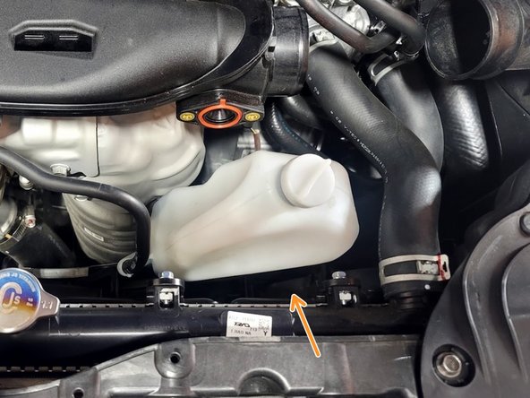
Pull up on reservoir to free from bracket and relocate as shown
-
-
-
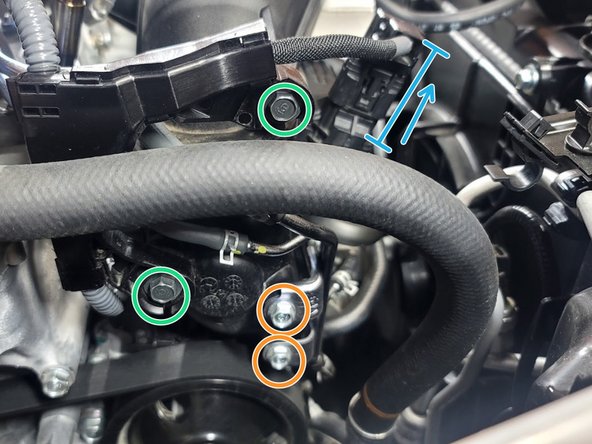
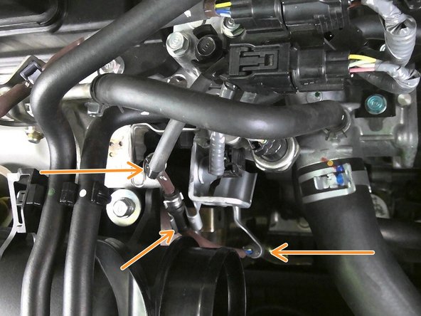
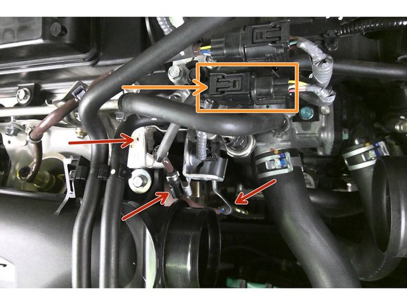
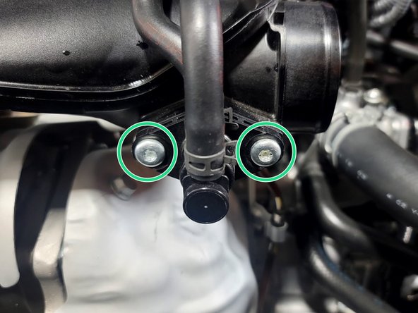
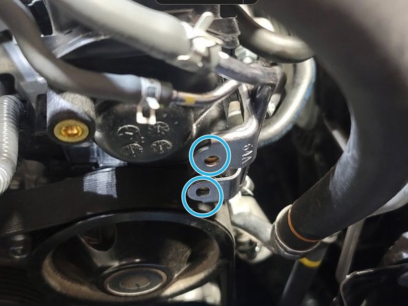
Use 10mm socket and ratchet to remove two (2) bolts from vacuum bracket
-
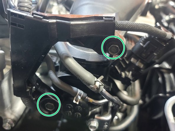
Use 10mm socket and ratchet to remove two (2) bolts from wiring loom
-
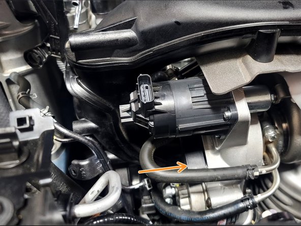
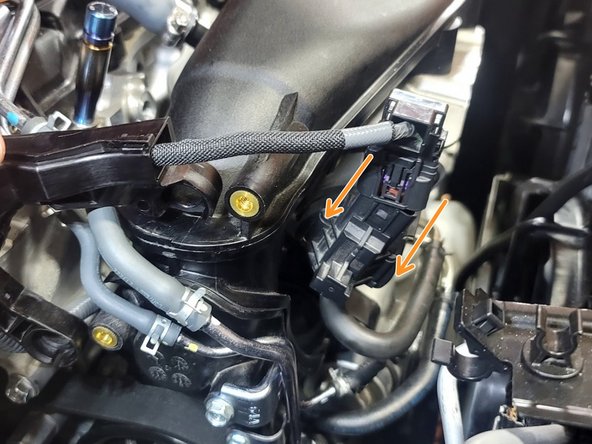
Unplug waste gate actuator by pushing the very top of the clip in with one finger and pulling the plug out with the other hand
-
Set wiring loom out of the way
-
-
-
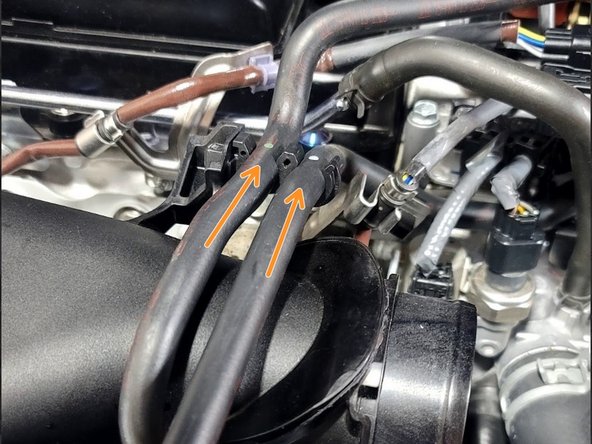
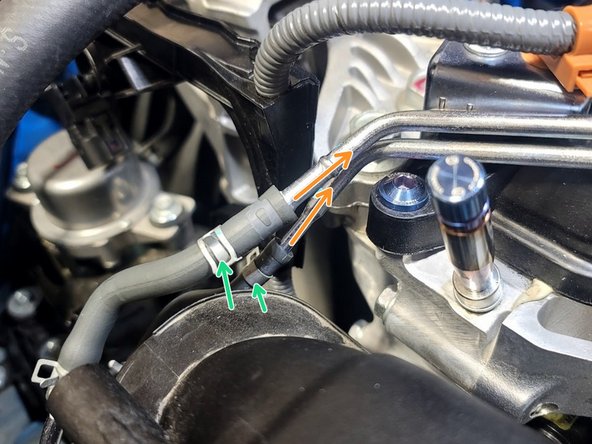
Use pliers to slide the two (2) hose clamps up the rubber hose
-
Twist each hose to break adhesion to metal tube then and pull both hoses off
-
Use hose pliers if you have them, it's easier
-
Use caution to avoid tearing rubber but it can take some force to free hoses
-
Set hoses out of the way
-
-
-
Use caution not to bend or damage A/C line while removing TIP
-
Be careful not to damage A/C line
-
Remove bolt with 12mm socket, 3" extension, and ratchet
-
Remove nut with 12mm socket, 3" extension, and ratchet
-
OE Turbo Inlet Pipe will wiggle freely now
-
-
-
Unfortunately Honda used a single use hose clamps for the turbo inlet pipe. These are difficult to remove
-
Use caution not to damage rubber lines. This is tricky
-
You can use a grinder, Dremel, or perhaps even shears to remove this single use clamp. We prefer Dremel
-
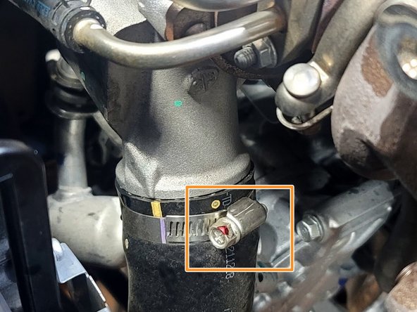
Remove Clamp Shown
-
Partially cut through band of clamp. The idea is to remove enough material that the clamp will break
-
Place flat head screwdriver under cut. If cut enough band will break pretty easily with a bit of pressure
-
-
-
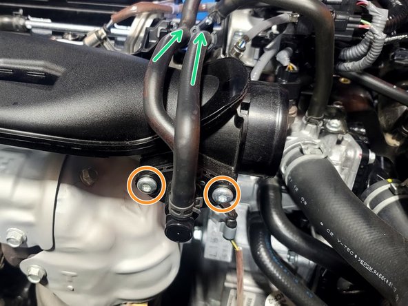
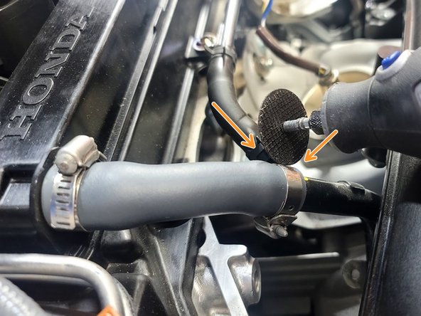
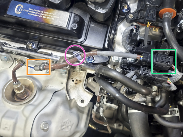
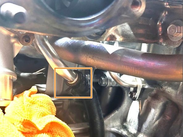
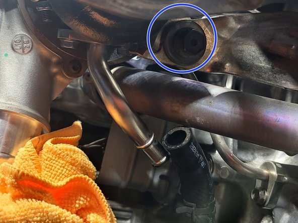
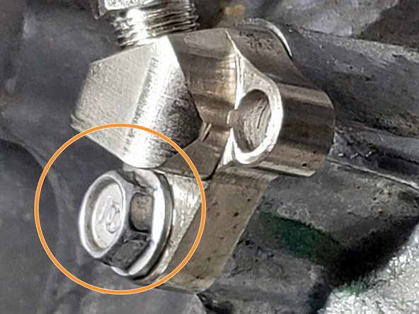
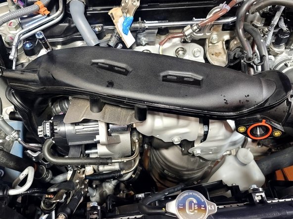
Pop crank breather hose off Image 1
-
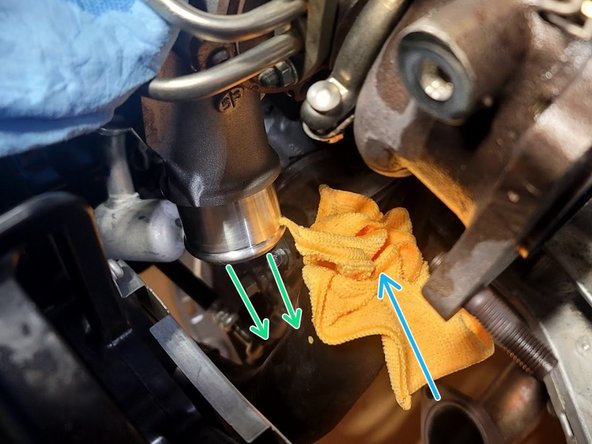
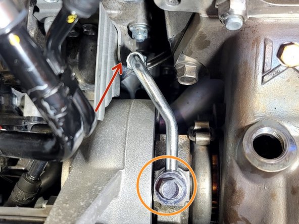
Use caution as you proceed to minimize coolant leaks
-
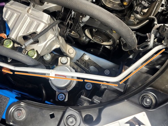
Pinch off coolant line in a manner similar to what is shown
-
There are various other tools and ways to accomplish this, like pinch pliers
-
Put towel under coolant line to catch leak
-
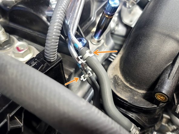
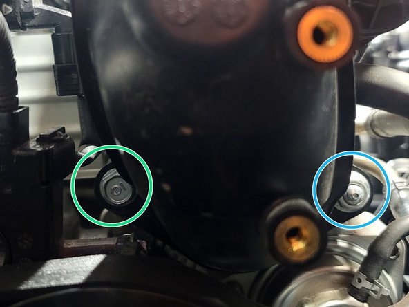
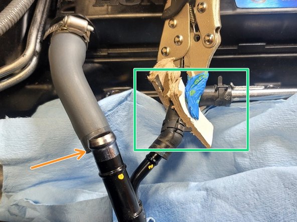
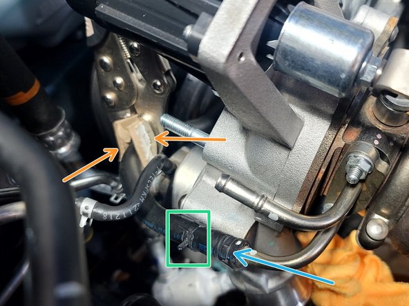
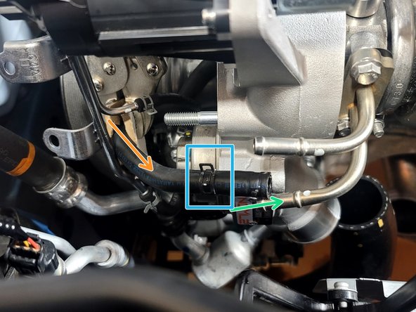
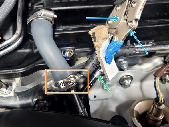
Use pliers to slide clamp out of the way as shown
-
Remove rubber upper coolant hose from the TIP hard line
-
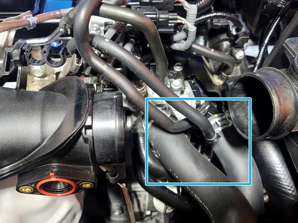
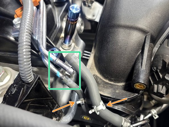
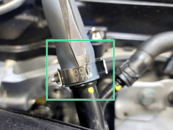
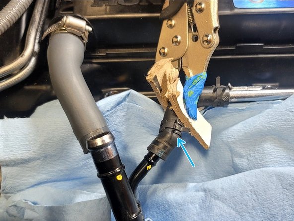
Place towel under the other end of the same line. Slide clamp (blue box) up hose using pliers and remove rubber hose from hard line
-
-
-
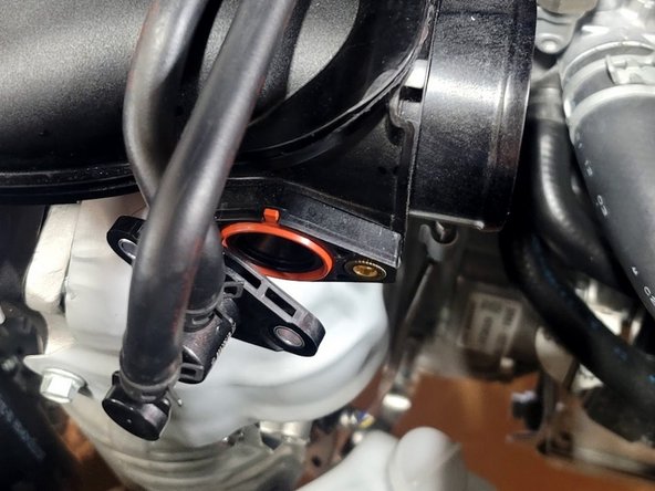
Plug coolant line attached to TIP with finger while removing TIP so as to avoid further coolant spills
-
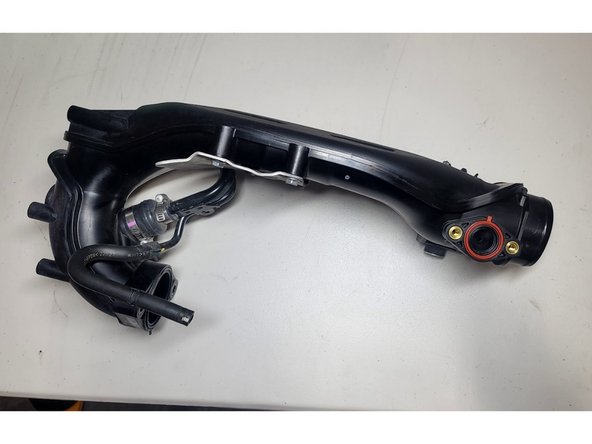
Remove OE TIP from car and set aside
-
-
-
Return coolant tank to it's original position to get it out of the way
-
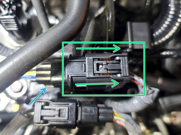
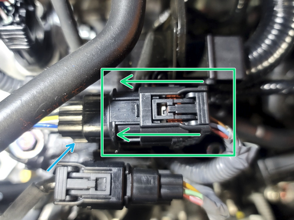
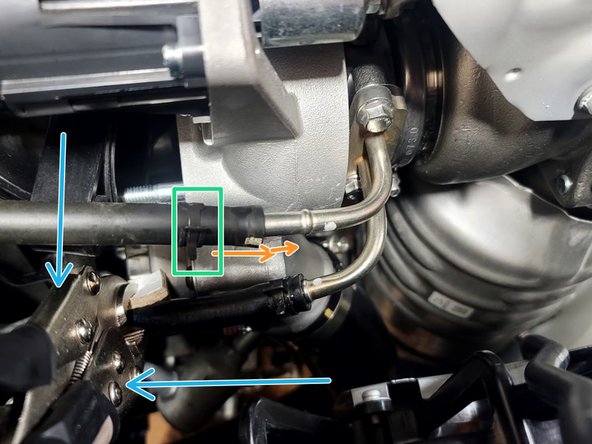
Pop primary O2 sensor wire out of clip
-
Use Pliers to pinch loom clamp to free wires
-
Pinch clip and pull right on right side of connector as shown to disconnect wiring loom from sensor
-
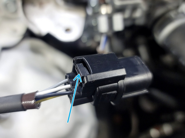
Pinch tab of left side of connector at very end and bottom of plug to free it from the bracket
-
-
-
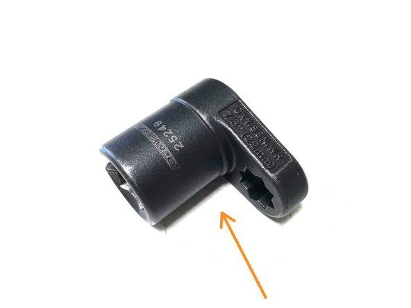
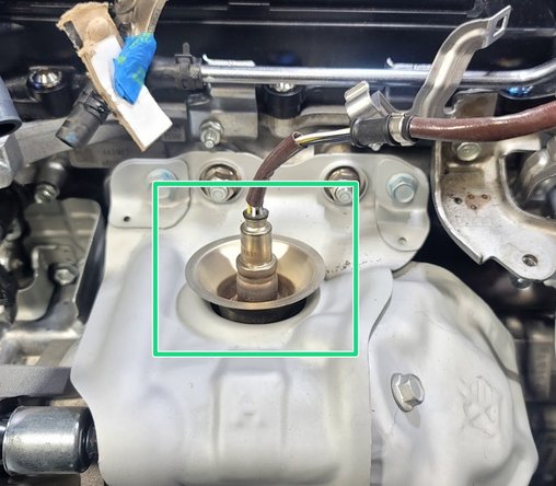
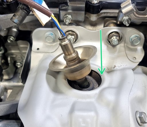
Use a 22mm specialty oxygen sensor socket to loosen the primary oxygen sensor
-
It need not be this exact socket
-
Use caution not to twist wires too much
-
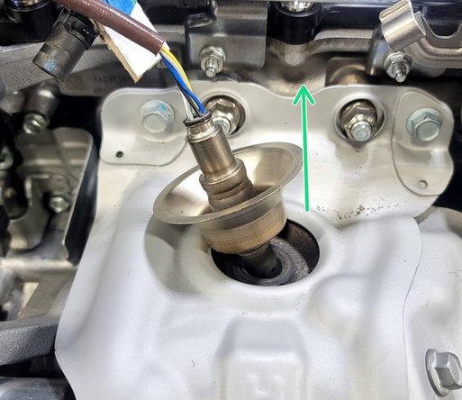
By hand, remove O2 sensor from turbine housing
-
-
-
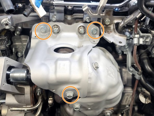
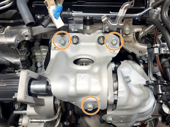
Remove three (3) bolts with 12mm socket and ratchet
-
Remove heat shield and set aside
-
-
-
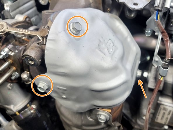
Use a 12mm socket and ratchet to remove the three (3) x bolts securing the upper heat shield to the factory downpipe
-
Remove OEM heat shield & set aside for later use
-
-
-
Undo the clip for the secondary O2 sensor plug and remove the plug
-
Remove the wire from the three (3) locating tabs for the secondary O2 sensor
-
These are three (3) metal tabs that hold the O2 sensor wire in place. By lightly bending them, the O2 sensor wire can be disconnected from the wire bracket
-
-
-
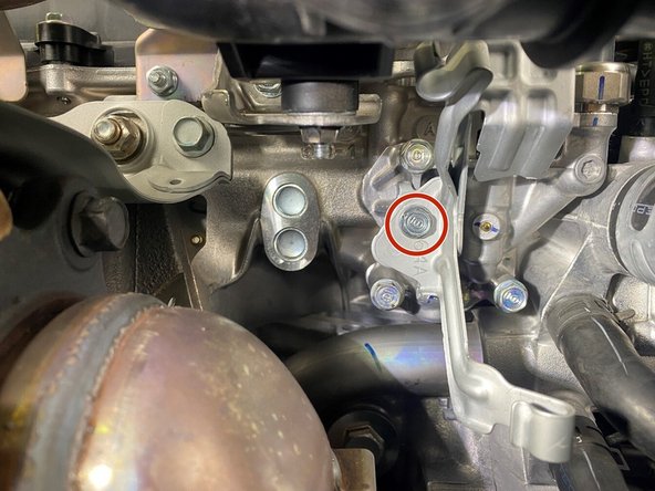
Using a ratchet with a 4" extension and a 10mm socket, remove the one (1) 10mm bolt securing the secondary O2 wiring bracket
-
Remove the bracket and set aside for later use
-
-
-
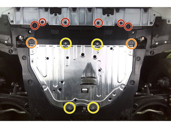
Civic shown. Integra is slightly different
-
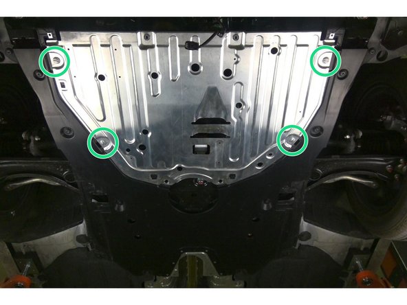
Remove plastic portion of skid tray as follows:
-
Six (6) push clips from front
-
Use a flathead screwdriver or a prying tool
-
Using a screwdriver, remove metal portion of skid tray as follows:
-
Two (2) black philips head screws
-
Four (4) silver phillips head screws
-
Four (4) flat head screws
-
-
-
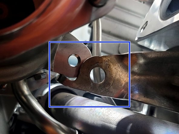
Remove the four (4) 14mm bolts securing the two lower downpipe support brackets
-
DO NOT discard the bolts. The four bolts will be reused
-
-
-
Using a 3/8" drive ratchet and a 14mm socket, remove all three (3) nuts securing the downpipe studs
-
The stud may come out of the downpipe with the nut. This is OK
-
Separate the front pipe from the downpipe, the front pipe will remain in place
-
-
-
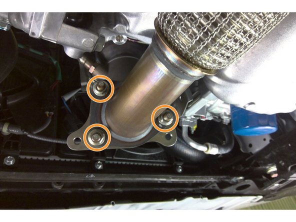
Prior to attempting removal of the downpipe, liberally apply penetrating lubricant (PB Blaster, Deep Creep, etc.) on the downpipe nuts & bolts
-
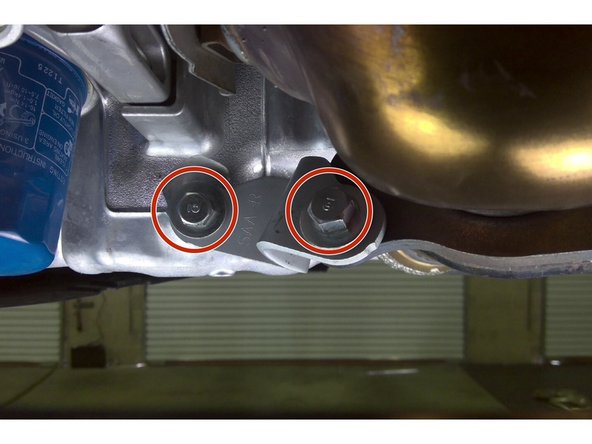
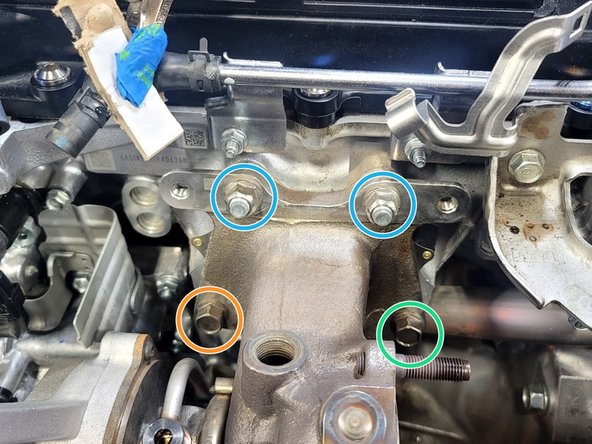
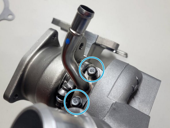
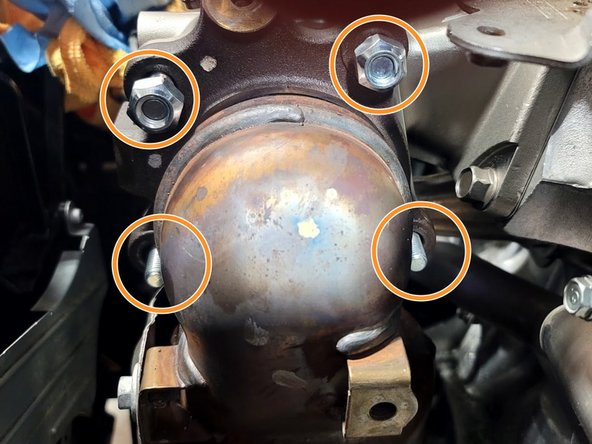
Using the 3/8" drive 14mm socket and ratchet along with the aid of a breaker bar, remove the following from the turbine side of the turbocharger:
-
Two (2) 14mm bolts
-
Two (2) 14mm nuts
-
Be careful and take your time to avoid breaking a stud inside the turbine housing. Trust us, a broken stud is going to make this install a lot longer. It will require you remove the stud by removing the OEM turbocharger and sourcing new studs AND hardware from Honda
-
Pull the downpipe up out of the engine bay, being careful not to damage the wiring harness on the secondary oxygen sensor
-
Set aside downpipe for later reinstallation
-
Remove gasket from turbine housing. This will not be reused
-
-
-
Use 10mm socked and ratchet or Phillips screwdriver to remove clamp from FMIC Inlet hose
-
Slide inlet hose off turbocharger compressor cover
-
Stick a rag in the inlet hose as shown to keep coolant out of it and tuck inlet hose out of the way
-
-
-
Pinch rubber coolant line to prevent leak
-
Slide clamp up hose
-
Remove rubber coolant line from lower hard line on turbo
-
-
-
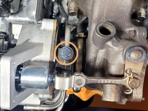
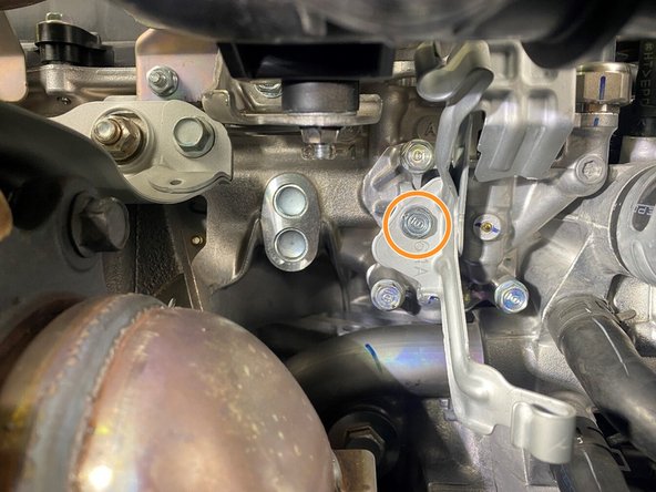
Use 12mm socket and ratchet to remove the oil feed banjo bolt
-
Stock Oil feed bolt is reused for GIN Journal Bearing (JB)
-
New oil feed bolt is supplied with GIN Ball Bearing (BB)
-
-
-
Use pliers to slide clamp down rubber oil return hose
-
Slide rubber hose off hard line
-
Use clean rag to wipe excess oil from oil drain hard line
-
-
-
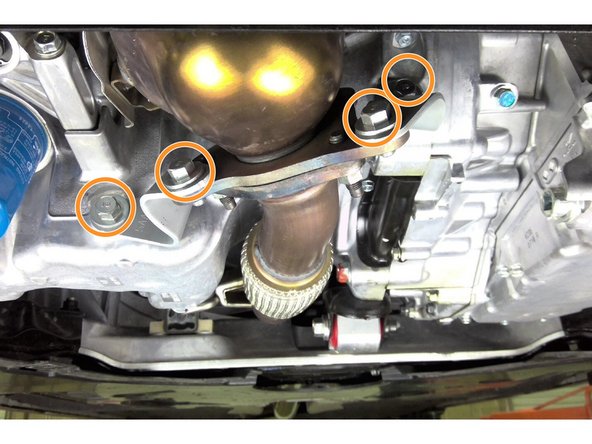
Prior to attempting removal of the turbo, liberally apply penetrating lubricant (PB Blaster, Deep Creep, etc.) on the turbo nuts & bolts
-
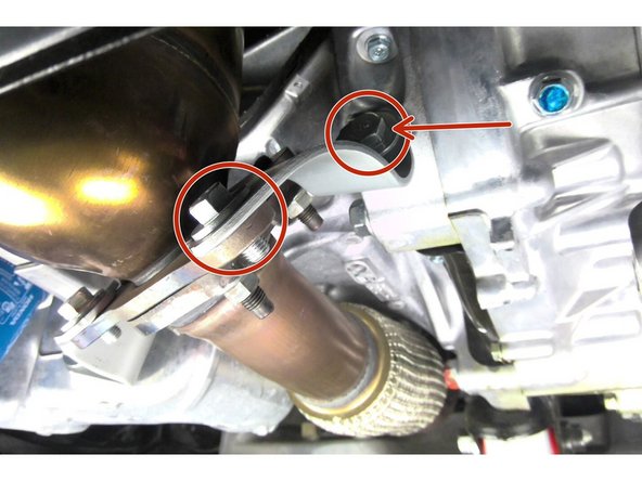
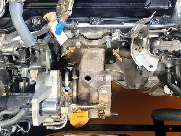
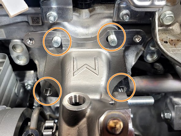
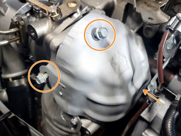
Use 14mm wrench to break loose lower left bolt from turbine housing
-
Using the 3/8" drive 14mm socket and ratchet, along with the aid of a breaker bar if necessary, remove the following from the turbine housing of the turbocharger:
-
The remaining lower bolt
-
Two (2) upper nuts
-
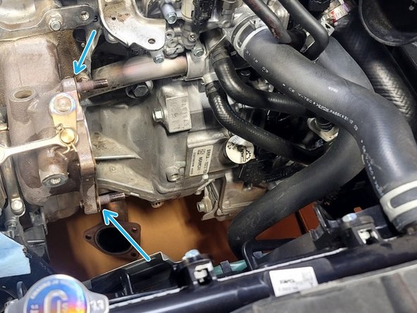
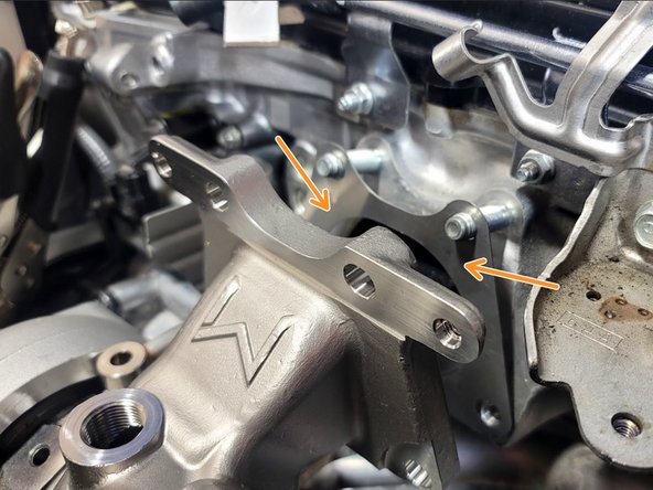
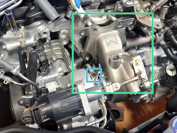
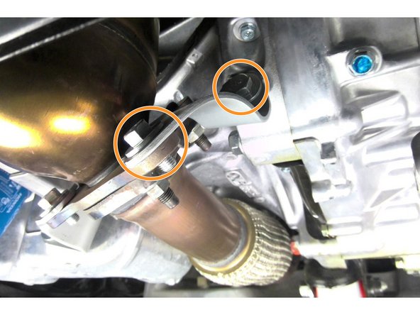
Using 14mm socket, and breaker bar if needed, remove bolt and washer from turbo support bracket
-
-
-
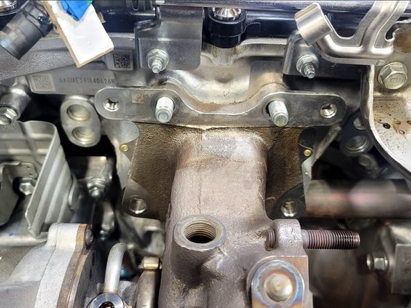
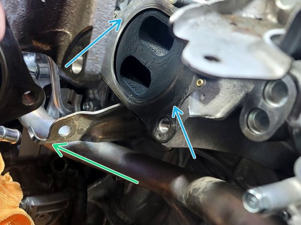
Wiggle turbocharger as you rotate the assembly off the two studs remaining in the head
-
There is a hook on the lower support bracket that can make it difficult to remove the turbo assembly
-
Remove gasket. It will not be reused
-
Set OE turbocharger assembly on clean work surface to begin swapping parts
-
-
-
Set OE turbo and GIN turbo side by side
-
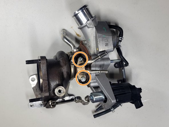
Remove both nuts from OE coolant hardline with 10mm socket and ratchet
-
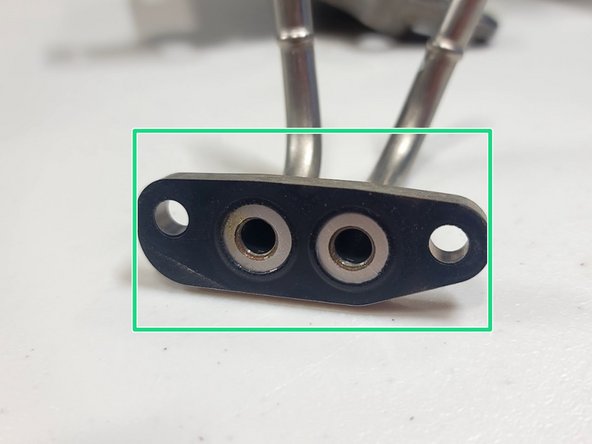
OE gasket should come off with hardlines. This is reused
-
Install hardlines using OE hardware on GIN turbocharger. Torque to 9-11 ft-lbs
-
-
-
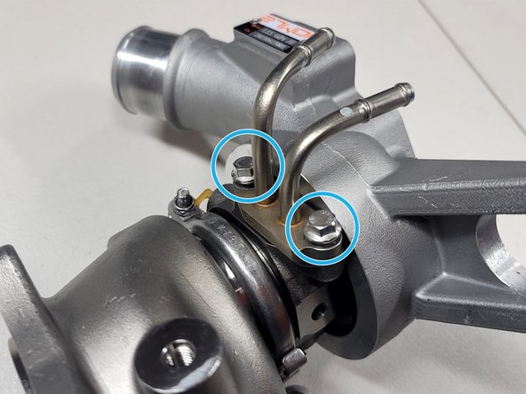
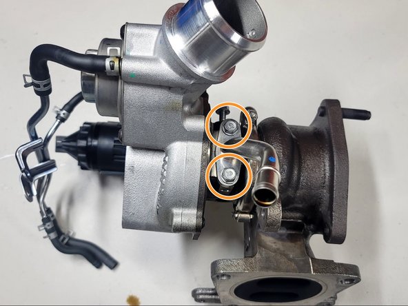
Remove both bolts from OE drain with 10mm socket and ratchet
-
OE gasket should come off with the drain line. This is reused
-
Install oil return using OE hardware on GIN turbocharger. Torque to 9-11 ft-lbs
-
Make sure to orient the drain line correctly
-
-
-
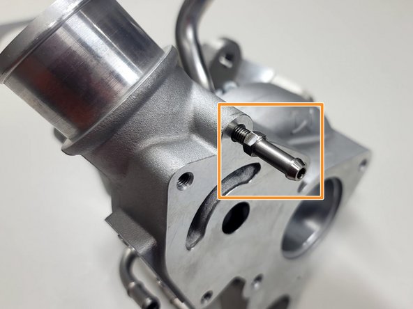
Install provided nipple using 8mm wrench until snug
-
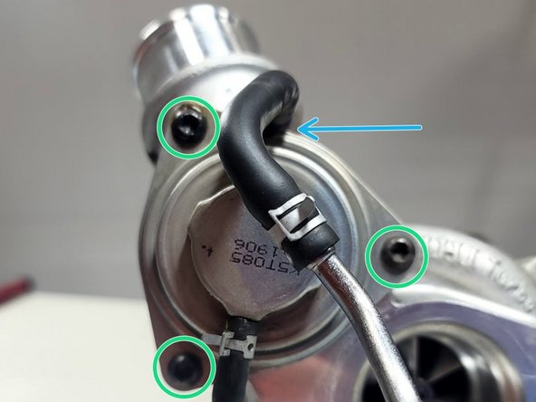
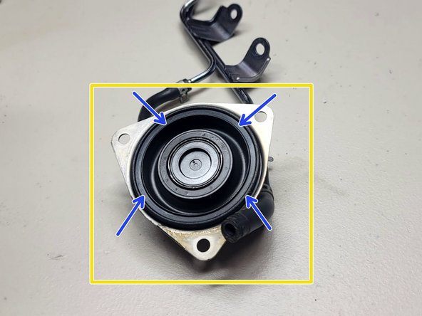
Remove three (3) screws using T30 Torx bit from bypass valve (BPV)
-
Slide clamp (blue arrow) using pliers up rubber hose
-
Twist off rubber hose and remove BPV and vacuum hard line assembly from OE turbo
-
Wipe clean rubber gasket in BPV
-
Use extra caution to make sure BPV is oriented correctly or vacuum lines won't route correctly later
-
Install BPV on GIN turbo exactly like it was on OE turbo by tightening the three Torx screws evenly in a crisscross pattern
-
Connect vacuum line to nipple by sliding hose then clamp over nipple
-
-
-
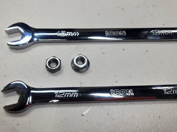
Gather provided 13mm nut, a 12mm and 13mm wrench along with OE TIP flange nut
-
Tighten both nuts into each other as shown
-
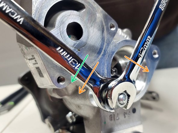
Use 13mm wrench on inner provided nut to remove stud from compressor cover
-
Use 13mm wrench to tighten stud into same location on GIN turbocharger until snug
-
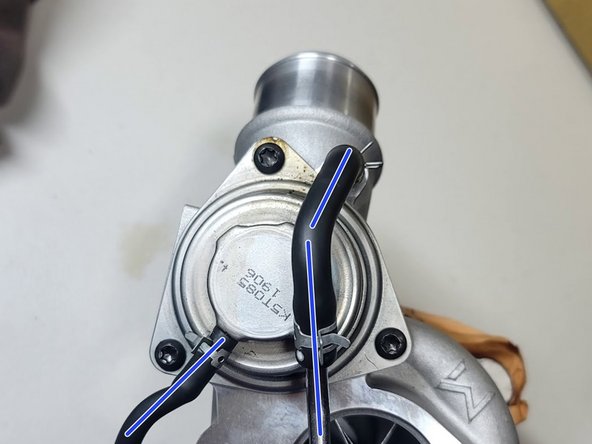
This is a good time to make sure BPV was installed correctly
-
Make sure vacuum lines are routed as shown
-
-
-
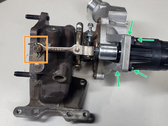
Pull pin from wastegate arm using pliers
-
Remove four (4) screws using T20 Torx bit from wastegate actuator (WGA)
-
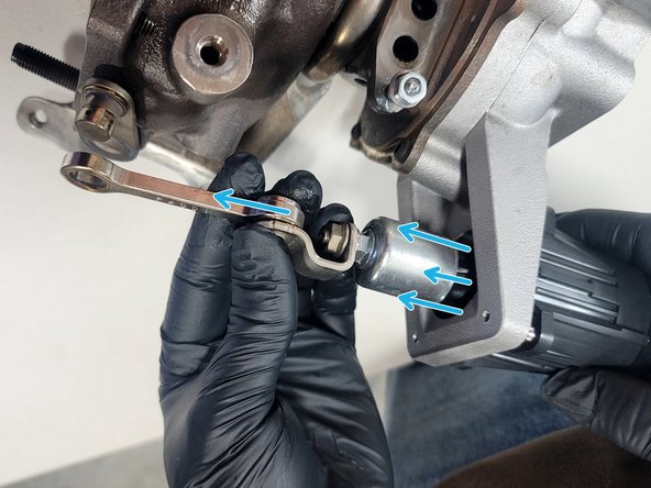
Pull WGA to extend arm then pull arm off wastegate flapper arm
-
Swap assembly over to GIN turbo exactly like OE
-
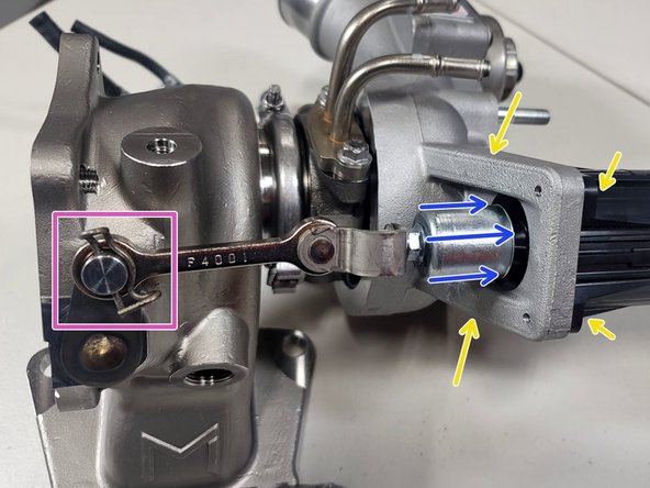
You may need to compress WGA to get arm over pin on GIN.
-
Reinstall pin on wastegate arm
-
Reinstall four (4) screws using T20 Torx to snug
-
-
-
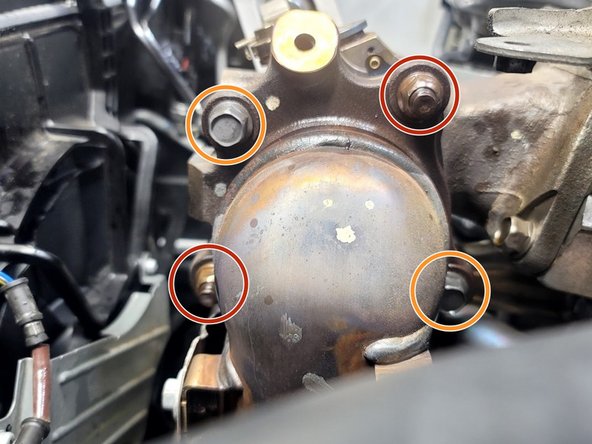
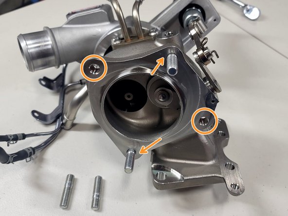
Install four (4) provided studs in turbine housing by hand, as shown
-
-
-
Hang provided gasket from studs as shown
-
Place turbo over studs as shown
-
Make sure to clear oil feed line
-
Turbine housing has to be on top of the support bracket to get the turbo on the studs
-
-
-
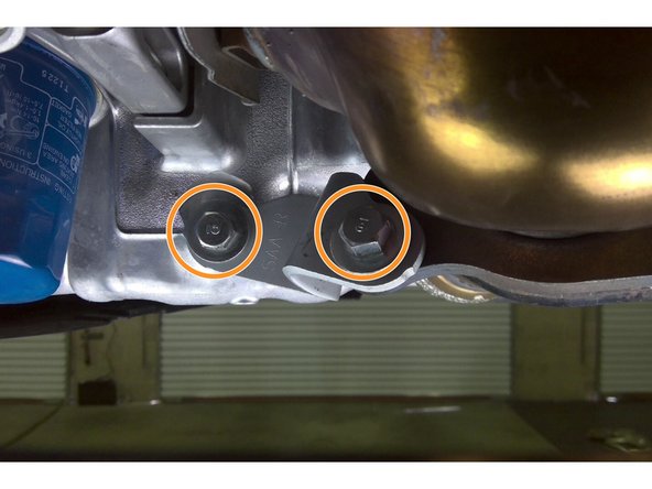
Following reverse of removal, hand thread two (2) OE nuts and two (2) OE bolts in their correct location as shown
-
Torque Nuts and Bolts using star pattern to distribute force evenly. Torque to 42-48 ft-lbs
-
-
-
Reinstall rubber oil drain hose to turbo drain line
-
Slide hose clamp into position using pliers
-
-
-
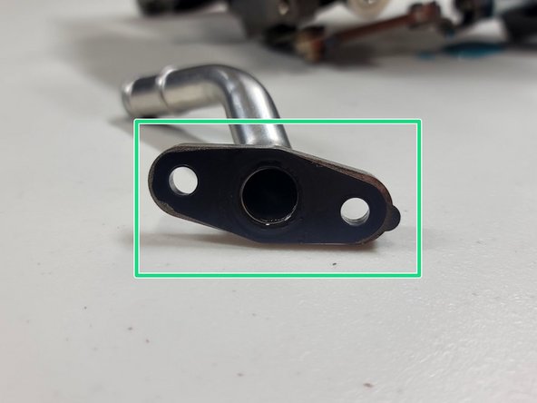
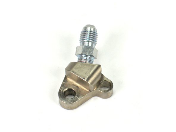
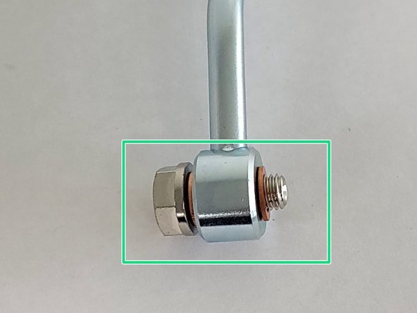
Locate the provided oil feed block fitting
-
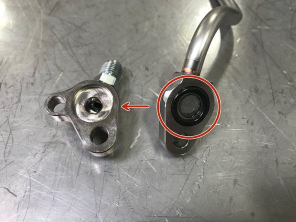
Locate the OE oil feed tube. Use a small flat head screwdriver to remove the O-ring/screen from the OE oil feed tube
-
Be careful to not damage the O-ring during removal and installation
-
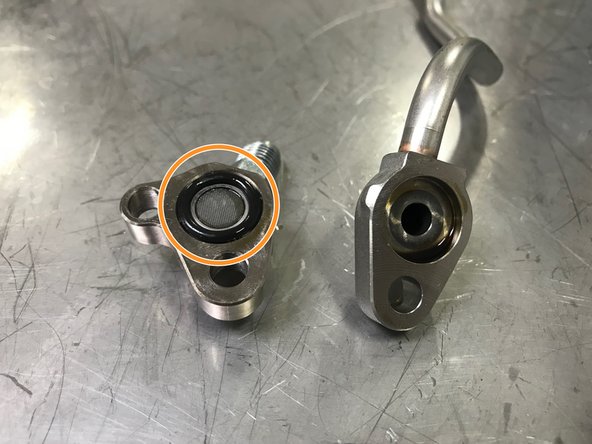
Install the O-ring/screen into the oil feed block fitting as shown
-
-
-
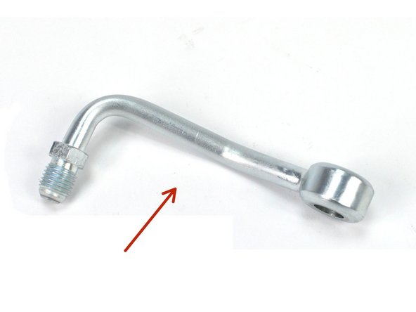
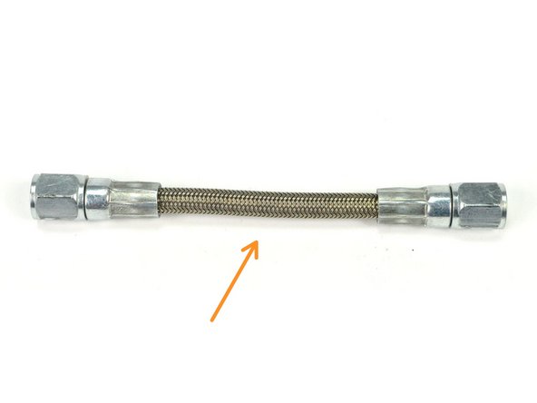
Locate the provided oil feed hard line and oil feed braided hose
-
Oil Feed Banjo Hard Line
-
Oil Feed Braided Hose
-
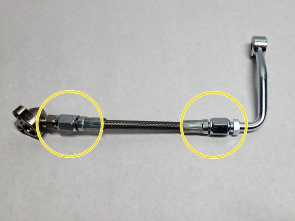
Attach the both ends of braided hose
-
Use a 12mm and 14mm wrench to tighten the braided hose. Hand tighten then use wrenches to tighten an extra 1/8 - 1/4 turn
-
-
-
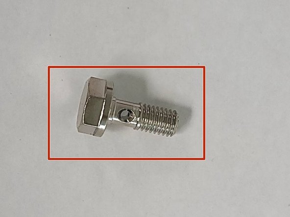
Must use proper oil feed bolt. For Journal Bearing (JB) use OE bolt and provided crush washers
-
For Ball Bearing (BB) use provided bolt and provided crush washers
-
Seat banjo bolt with a crush washer on either side of oil feed banjo
-
-
-
Place the assembled oil feed line onto the turbo as shown
-
Install the oil feed banjo bolt and crush washers. There should be one crush washer on each side of the oil feed bolt connection
-
Route the oil feed block fitting and braided hose as shown
-
Hand tighten the oil feed banjo bolt into the turbo as shown
-
Verify that the upper and lower copper crush washers are on the oil feed banjo bolt
-
-
-
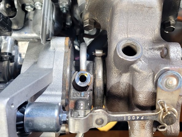
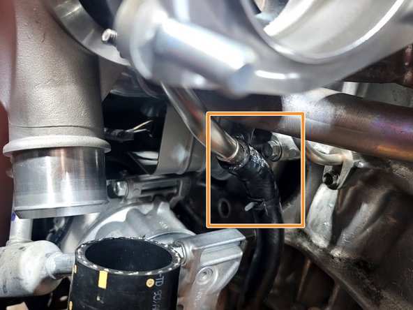
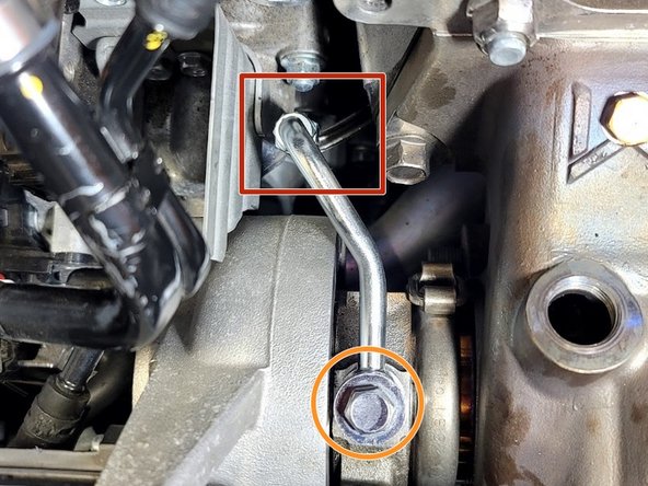
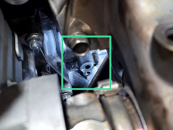
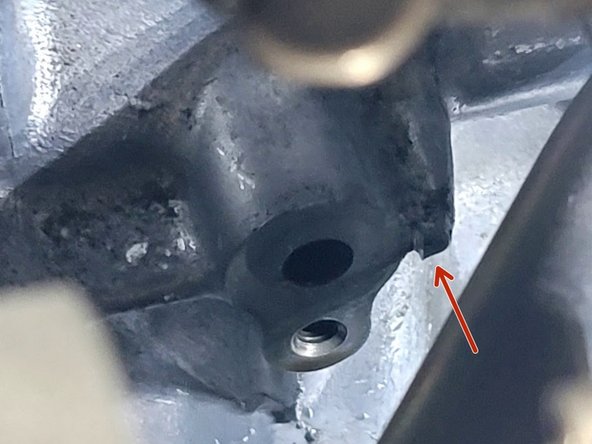
Locate the oil feed block connection location shown in the first image
-
The small protrusion is critical and must align with the hole on the side of the oil feed block fitting
-
Align the protrusion and the loop on the block fitting then install the OE 10mm bolt. Torque to 9-11 ft-lbs
-
-
-
Verify that the oil feed braided hose is not touching or rubbing any components
-
Use a 14mm socket and torque the oil feed banjo bolt to 12 ft-lbs
-
Do not over torque provided oil feed banjo bolt. It could break
-
If touching is occurring loosen the oil feed banjo bolt and adjust the position
-
-
-
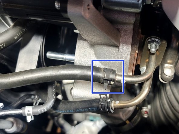
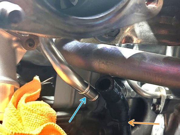
Route coolant line through vacuum hard line as shown
-
Slide rubber coolant line over lower hard line
-
Using pliers, slide clamp over coolant line to secure in place
-
-
-
Slide rubber inlet hose onto turbocharger
-
Move clamp into position to secure inlet hose
-
Use 10mm socked and ratchet or Phillips screwdriver to tighten clamp
-
-
-
Attach the downpipe to the turbo using a 17mm socket and ratchet on the four (4) provided M10 crimp nuts. Torque to 42-48 ft-lbs
-
-
-
Using a ratchet with a 4" extension and a 10mm socket, reinstall the one (1) 10mm bolt securing the secondary O2 wiring bracket
-
-
-
Re-route the secondary O2 sensor wire harness back into the appropriate tabs, securing the black round spot in the tabs
-
Clip the secondary O2 sensor plug back into the harness
-
-
-
Reinstall the OEM upper heat shield using the three OEM bolts. Torque to 18 ft-lbs.
-
-
-
Using a 3/8" drive ratchet and a 14mm socket, reinstall all three (3) nuts securing the downpipe studs Torque to 40 ft-lbs.
-
-
-
Reinstall the four (4) 14mm bolts securing the two lower downpipe support brackets as shown Torque bolts to 33 ft-lbs
-
-
-
Reinstall the skid tray:
-
Six (6) push clips from front
-
Two (2) black philips head screws
-
Four (4) silver phillips head screws
-
Four (4) flat head screws
-
-
-
Reconnect three (3) bolts with 12mm socket and ratchet. Torque to 15-18 ft-lbs
-
-
-
By hand, reinstall O2 sensor into turbine housing
-
Use a 22mm specialty oxygen sensor socket to secure the primary oxygen sensor
-
-
-
Plug in primary O2 sensor as shown
-
Pop loom clip back into bracket as shown
-
Press loom back into clamp as shown
-
-
-
Place TIP back in car as shown
-
Slide rubber upper coolant hose over hard line
-
Slide hose clamp into position to secure upper coolant line
-
Remove clamp preventing leak from lower coolant hose
-
-
-
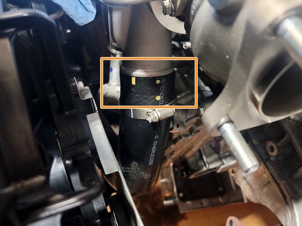
Reinstall crank breather hose using provided worm drive clamp as shown
-
Slide rubber coolant line onto hard line
-
Slide clamp in place to secure coolant line
-
Remove clamp preventing leak from upper coolant hose
-
-
-
Be careful not to damage A/C line
-
Wiggle OE TIP into position as shown
-
Reinstall both OE bolt and nut securing TIP to turbo with 12mm socket, 3" extension, and ratchet. Torque to 15-19 ft-lbs
-
Using 10mm socket and ratchet reconnect TIP to bracket near TIP inlet
-
-
-
Route rubber hoses as shown and insert them into the clips
-
Reinstall two (2) screws into Turbo Inlet Pipe (TIP) with T30 Torx Bit to secure EVAP valve
-
-
-
Slide both rubber vacuum lines over hard lines
-
Slice clamps over rubber lines to secure
-
Use 10mm socket and both OE bolts to reattach OE vacuum hard lines to TIP
-
-
-
Plug in WGA
-
Reinstall both OE bolts into wiring loom with 10mm socket and ratchet
-
Put OE coolant tank back into original position in bracket
-
-
-
Reinstall accordion intake tube and tighten clamps with 5.5mm socket
-
-
-
Some smell may be present on the first start as any residue in the exhaust burns off. This is normal and will not happen after the 2nd or 3rd heat cycle
-
Check the engine coolant level in the reservoir for the next few days as the air in the cooling system works itself out. Refill as needed
-
To get the best performance from your GIN Turbocharger, we highly recommend a custom tune
-
A custom tune for your specific vehicle with your specific modifications will provide the best performance for your Civic/Integra and the location you live in
-
You’ll run higher boost with Gin than the OE turbo. That could result in a hose popping off due to the increased boost. Any hoses with clamps removed during install should be properly secured. CEL Code P2187 or P2101 is a clue this might have happened.
-
-
-
A vehicle equipped with a larger performance turbocharger may require a change in the way it is driven. A properly tuned vehicle with a larger turbocharger definitely will
-
A properly tuned vehicle with a larger turbocharger will experience peak torque later in the RPM range. This may make the vehicle feel more sluggish in the the lower RPM range, approximately sub 3000rpm. However, peak power will also move higher in the RPM range and carry to redline
-
We recommend shifting at a higher RPM (~400rpm higher) to combat this feeling
-
A larger performance turbocharger will also create more pronounced turbo induction noises, your gas mileage may drop significantly for the first few tanks from you constantly wanting to hear the turbo spool
-
-
-
This completes the installation of your 27WON Performance Turbocharger
-
We hope you were impressed with your 27WON experience and love your new turbo for years to come. Email us at sales@27won.com or call us at 571-271-0271 with any questions or concerns
-
Please leave a review here: https://store.27won.com/2022-civic-integ...
-
Share your experience using #27WON on Instagram and Facebook
-