Introduction
In this installation guide we have provided step by step instructions to remove the OEM turbocharger and install the 27WON Performance Turbocharger.
Advisory:
- Working under the vehicle requires a safe and sturdy location for the vehicle to sit on jackstands.
- The exhaust piping, turbocharger, and cooling system will be hot after recent vehicle operation. Allow the vehicle to cool or use a fan to cool the exhaust components before working on the vehicle.
Tools
- 1gal - Honda Genuine Coolant
- Silicone Lubricant Spray
- WD-40
- Shop Towels/Rags
- Jack Stand × 2
- Hydraulic Jack
- Flat Head Screwdriver - Large
- Phillips Screwdriver - #2
- Tongue and Groove Adjustable Pliers
- Pliers - Small
- Socket 5.5mm
- Socket, 10mm
- Socket 12mm
- Socket 14mm
- Socket 17mm
- Ratchet Wrench Extension - Short
- Ratchet Wrench Extension - Long
- Ratchet Wrench
- Wrench, 10mm
- Wrench, 12mm
- Wrench, 14mm
- Wrench, 17mm
- Allen Wrench 3mm
- Allen Wrench 5mm
- Torque Wrench
- O2/Oxygen Sensor Socket
- Magnet on a Stick
- Vise Grips - Small × 3
- Small Needle Nose Pliers
- Socket 13mm
- Wrench, 13mm
Parts
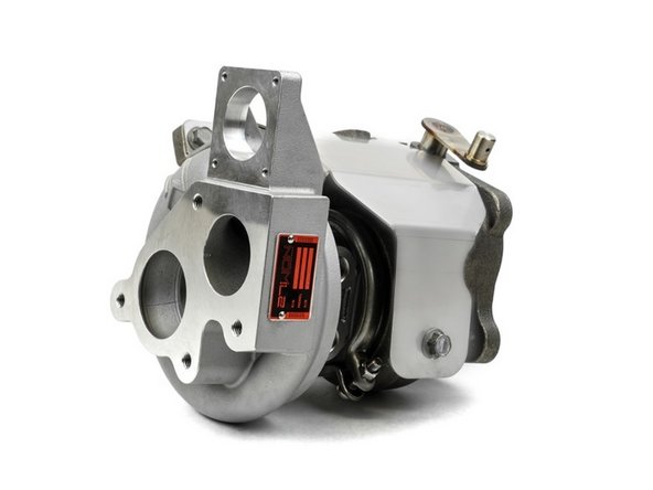
- L15-6-572 W2 Turbocharger
- M10x1.5 Stud × 4
- M10x1.5 Crimp Nut × 4
- Coolant Banjo Bolt × 2
- Oil Feed Banjo Bolt
- M14 Crush Washer × 4
- M10 Crush Washer × 2
- Coolant Pipe Upper
- Coolant Pipe Lower
- Oil Feed Pipe
- Oil Feed Braided Hose
- Oil Feed Block Fitting
- Turbine Gasket Inlet
- Turbine Gasket Outlet
- M8 x 1.25 Jam Nut
- M6 x1 .0 x12mm flanged bolt × 2
- M6x1.0x20mm Flange Bolt × 2
- M6x1.0 Flanged Nuts × 2
- M8x1.25x35mm Stud - Stainless Steel
- M8x1.25 Flange Nut - Stainless Steel
- Turbo Heat Shield
- Hood Prop Bracket
- M8x1.25x10mm Flange Bolt × 2
- M8x1.25x8mm Flange Bolt
-
-
First and foremost; THANK YOU for becoming a part of the 27WON Family. We hope to REDEFINE your experience of the aftermarket with the highest level Parts, Customer Service, Packaging, & Support
-
Relocating your hood prop is necessary to run the W2 & W3 turbo, failure to do so will result in damage to your WGA
-
-
-
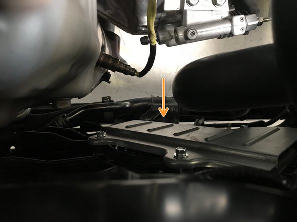
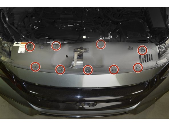
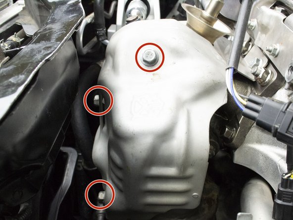
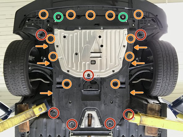
Locate the engine skidtray to gain access to the downpipe and front-pipe
-
Use 5mm Allen to remove the two (2) bolts shown in green circles
-
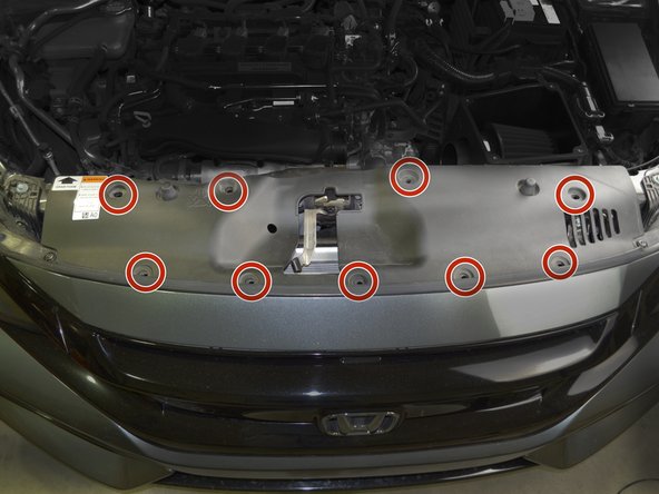
Use 10mm socket & ratchet to remove the seven (7) bolts shown in red circles
-
Use a flathead screwdriver to remove the seventeen (17) plastic push-clips. Orange arrows identify the push-clips described in the next step (3)
-
-
-
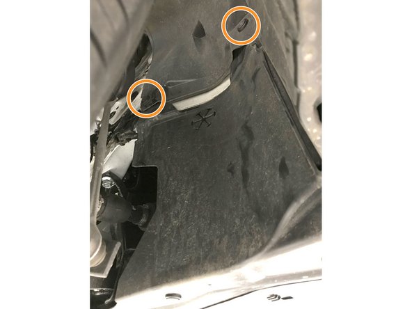
Use large flat head screw driver to remove push-clips on each side of skidtray
-
-
-
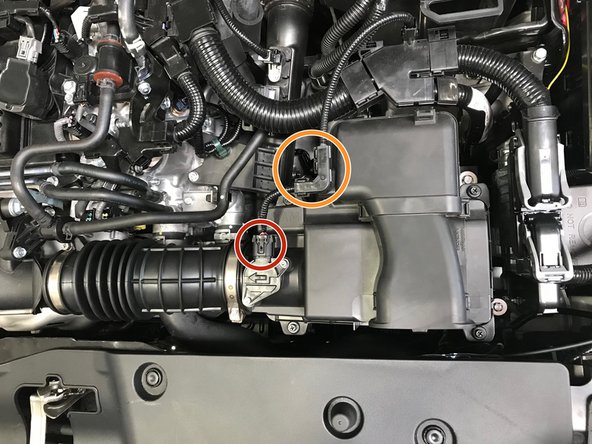
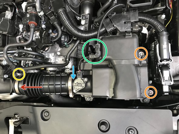
Disconnect the wiring harness from the MAF Sensor
-
Remove the wire cover from the airbox
-
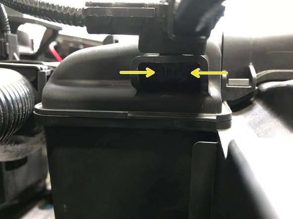
Use needle noise pliers to pinch the clips then pull the cover off the airbox
-
-
-
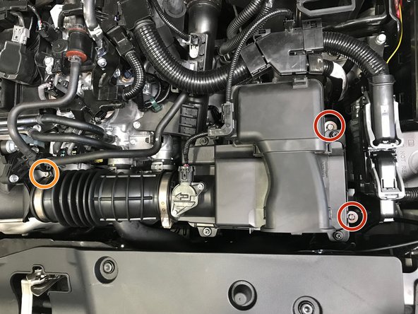
Use a 10mm socket, extension & ratchet to loosen the two (2) 10mm bolts
-
You can leave the bolts loose in position during airbox removal
-
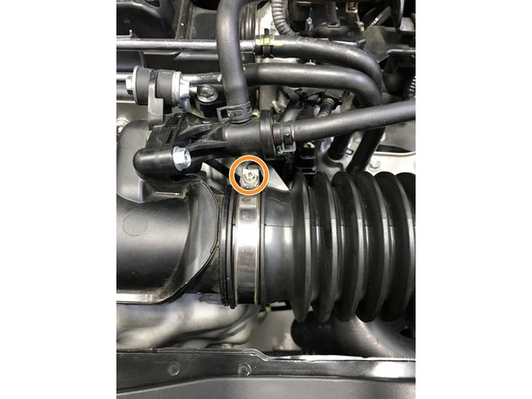
Use a 5.5mm socket to loosen the hose clamp
-
A small phillips screwdriver can be used, but is not recommend because the hose clamp head strips easily
-
-
-
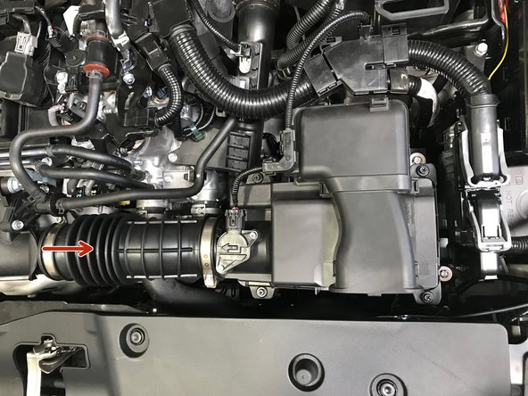
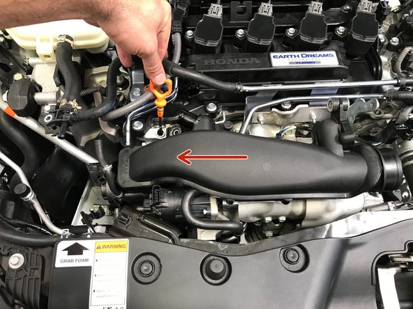
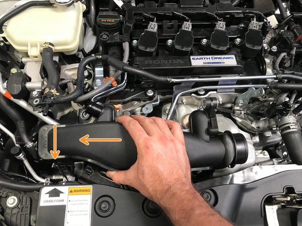
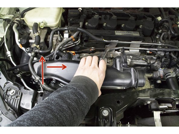
Pull the hose off the turbo inlet pipe in the direction of the arrow
-
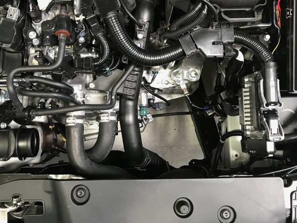
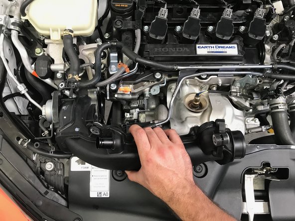
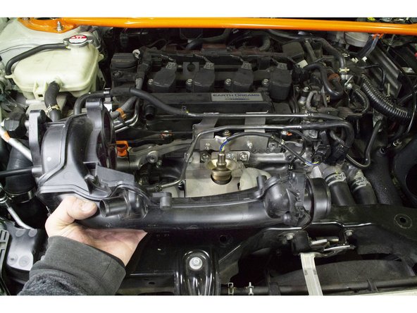
With the hose loose, remove the entire airbox from the engine bay
-
The result will look as shown in the second image
-
-
-
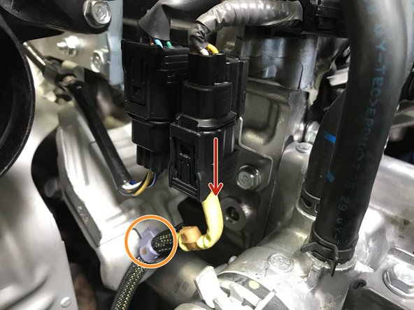
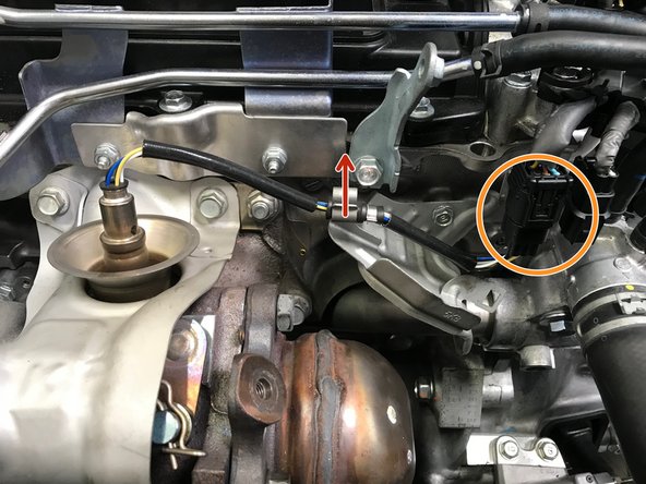
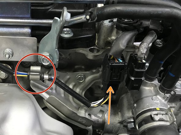
Disconnect the O2 sensor wire as shown with red arrow
-
Use small pliers to remove the purple clip from the bracket
-
Pinch the back side of the purple clip and push through the bracket
-
-
-
Verify that the bracket and radiator hose are not hot. If hot allow the vehicle to cool before proceeding
-
Moving the radiator hose allows improved clearance for downpipe removal
-
Use a 10mm socket & ratchet to remove the two (2) 10mm bolts holding the lower radiator hose in place
-
With the bolts removed, move the radiator hose upward and forward
-
-
-
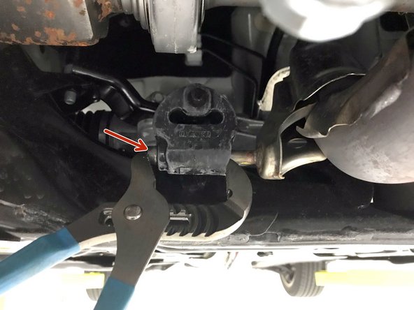
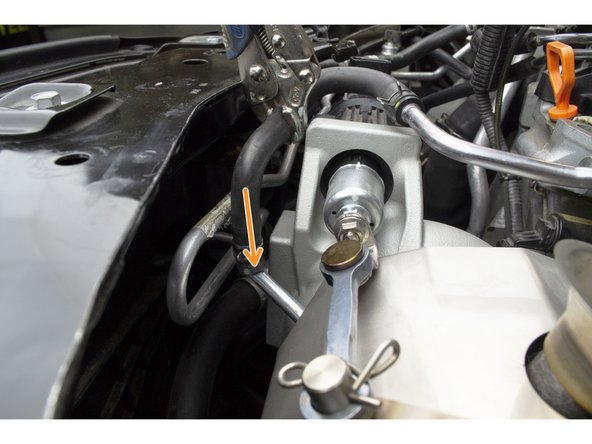
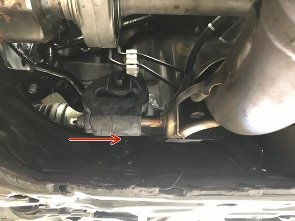
Apply a small amount of silicone spray to the end of the hanger rod (red arrow)
-
Use the tongue and groove pliers as shown to remove the rubber hanger
-
-
-
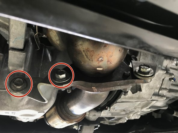
Use a 14mm socket and ratchet to remove the three OE nuts
-
It is possible that the stud will thread out of the downpipe flange. This is not an issue, the stud can be threaded back into the flange like a bolt
-
-
-
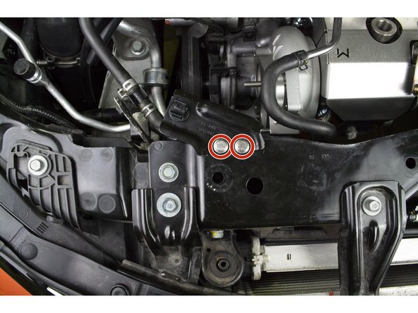
Verify that the brackets and coolant hose are not hot. If hot allow the vehicle to cool before proceeding
-
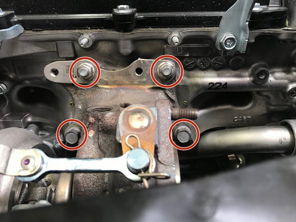
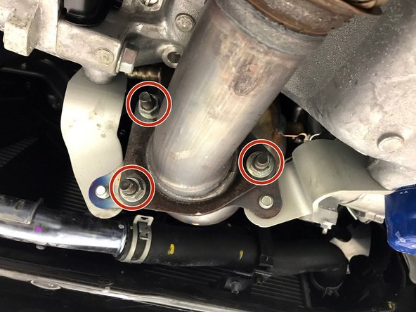
Use a 14mm socket & ratchet or wrench to remove the four (4) 14mm bolts as shown in red circles in two images
-
Remove the brackets from the vehicle
-
-
-
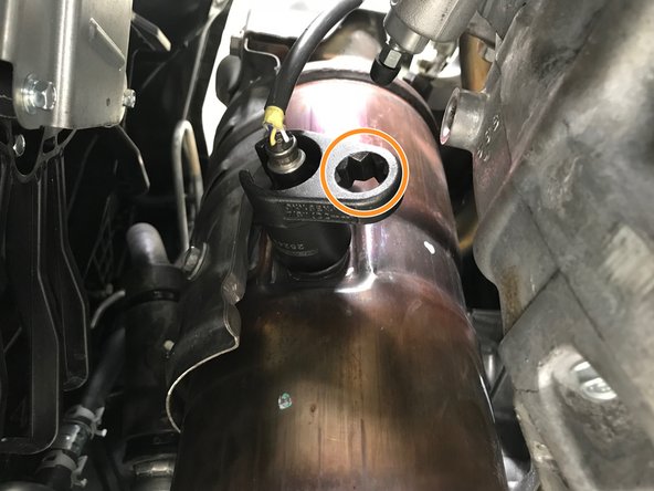
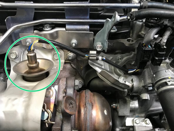
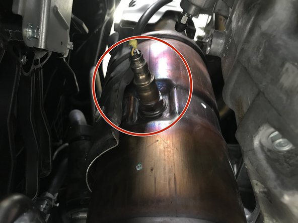
Locate the secondary O2 sensor on the downpipe
-
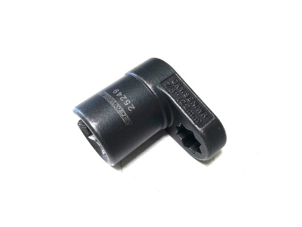
Locate the specialty socket - 22mm or 7/8" O2 sensor socket
-
Use the ratchet wrench in the specialty socket to remove the O2 sensor
-
-
-
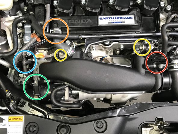
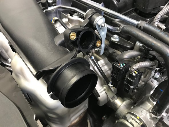
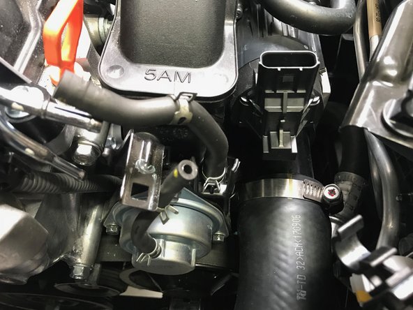
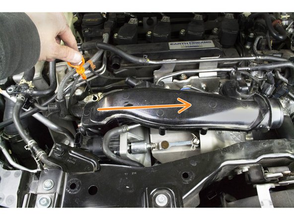
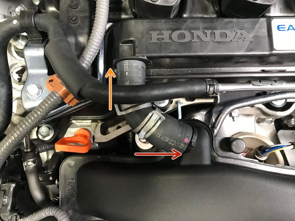
Going forward we will reference the black plastic pipe connected to the turbo as the "Turbo Inlet Pipe (TIP)"
-
The following components are identified for clarity in the following steps
-
EVAP Bleed Air
-
Valve Cover Breather Hose
-
TIP Mounting Points
-
Waste Gate Actuator (WGA) Wiring Connection
-
By-Pass Valve (BPV) Hoses
-
-
-
Use a 10mm socket & ratchet to remove the two (2) 10mm bolts
-
Pull the EVAP bleed air out of the TIP and set to the side
-
-
-
Use pliers to loosen the spring clamps. Slide the clamps towards the center of the hose
-
Pull the hose off the valve cover first
-
Pull the hose off the TIP second
-
-
-
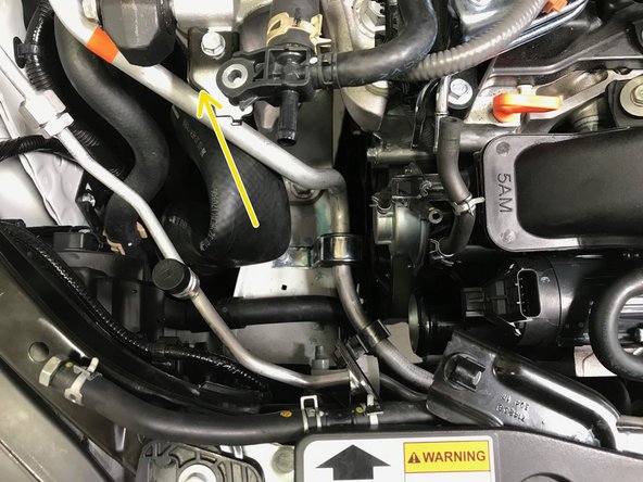
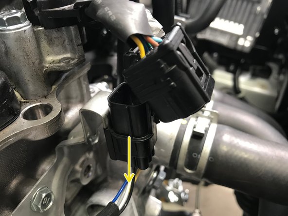
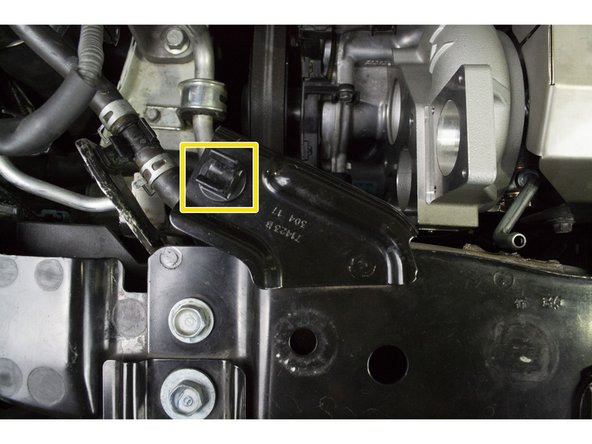
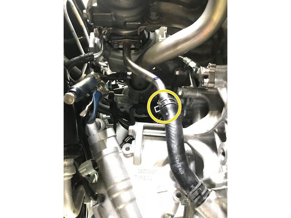
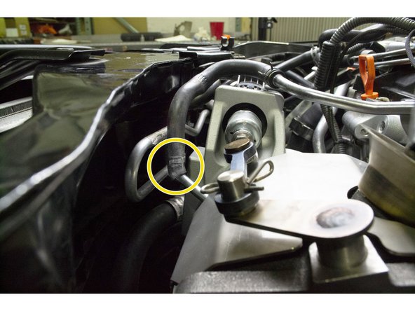
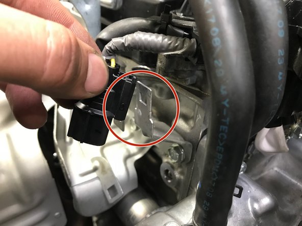
Disconnect the wiring from the Waste Gate Actuator (WGA)
-
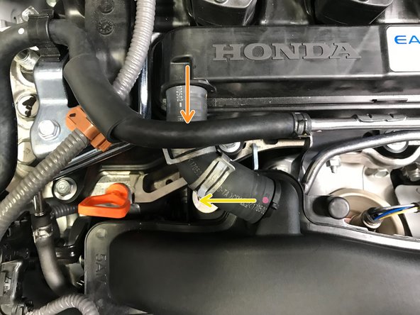
Locate the wiring loom
-
Press down on the small tab and pull the wiring loom from the bracket in the direction of the yellow arrow
-
Move the wiring harness towards the rear of the car out of the way
-
-
-
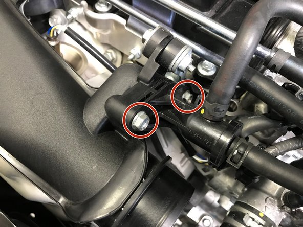
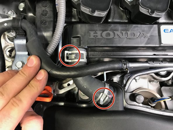
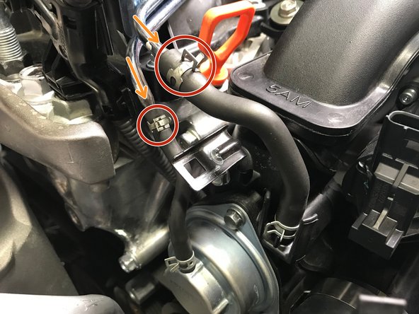
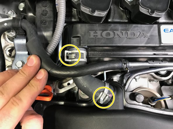
Use pliers to loosen the spring clamps. Slide the spring clamps with red circles towards the center of the hose
-
Pull the BPV hoses off the metal tubes in the direction of the orange arrows
-
-
-
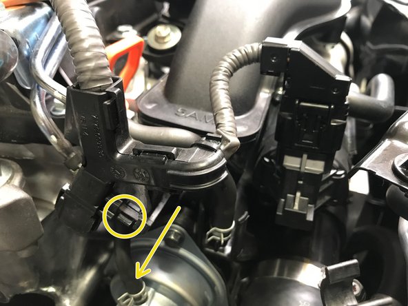
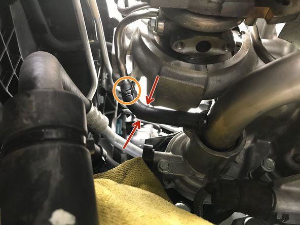
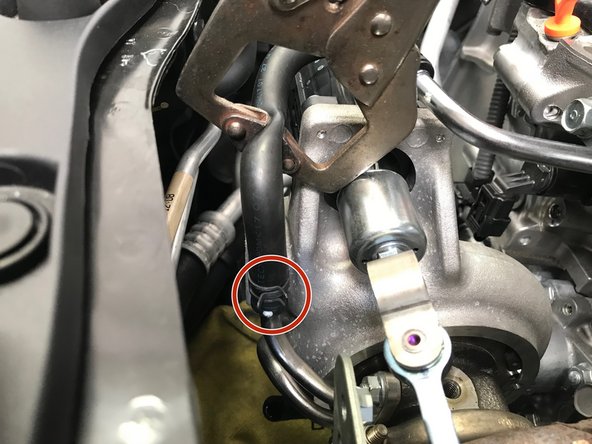
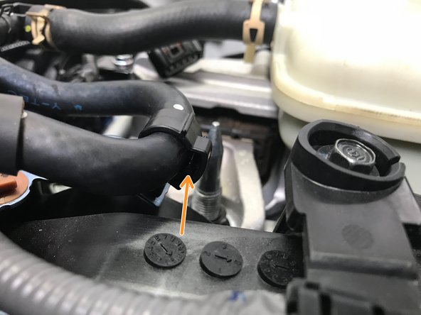
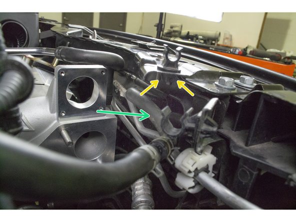
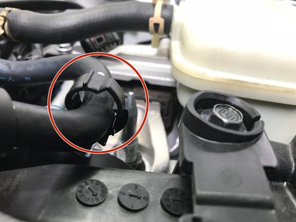
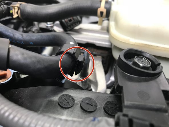
Use pliers to loosen the spring clamp. Slide the clamp towards the center of the of the hose
-
Pop the hose out of the plastic clip
-
Pull the hose off the plastic "T". Move the hose towards the front of the car out of the way
-
Some coolant may spill from the hose and "T" connection
-
Use a 10mm socket & ratchet to remove the bolt holding the "T" connection
-
-
-
Use a 10mm socket & ratchet or Phillips screwdriver to loosen the worm-gear clamp
-
Pull the hose off the TIP in the direction of the arrow
-
Remove the clamp from the hose so it does not get lost in the engine bay
-
Bend the hose towards the rear of the car. Stuff it into the fender liner out of the way
-
-
-
Use a 10mm socket & ratchet to remove the two (2) TIP mounting bolts
-
-
-
The next process is to remove the Turbo Inlet Pipe (TIP) from the vehicle.
-
We will first identify the hardware location and how to remove without losing the hardware in the engine bay
-
Second, we will show step by step images of physically removing the TIP for PDF users and a quick video for mobile users
-
-
-
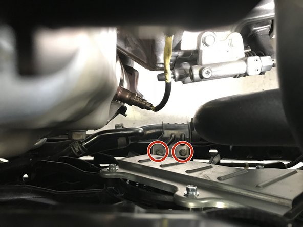
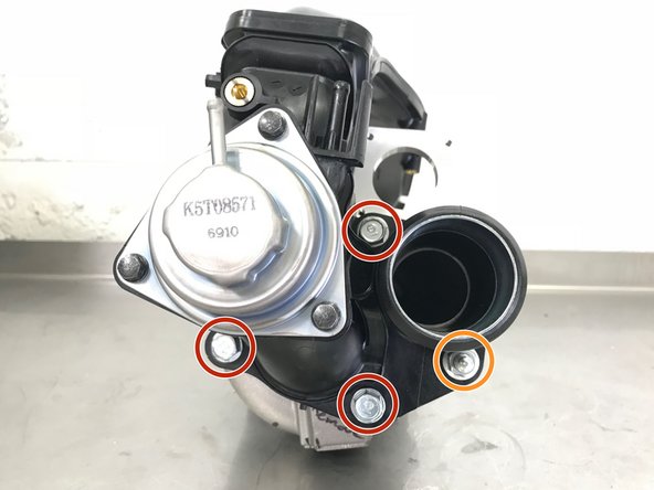
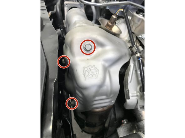
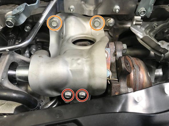
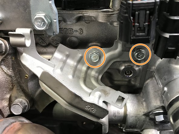
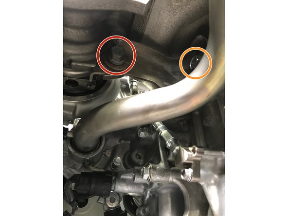
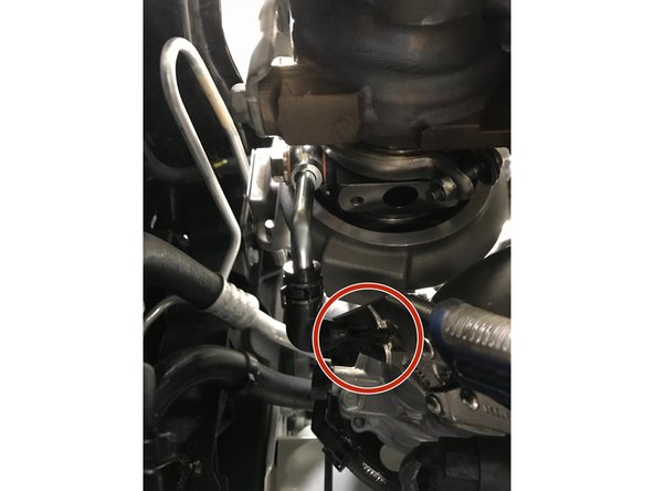
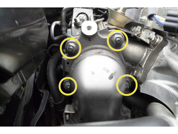
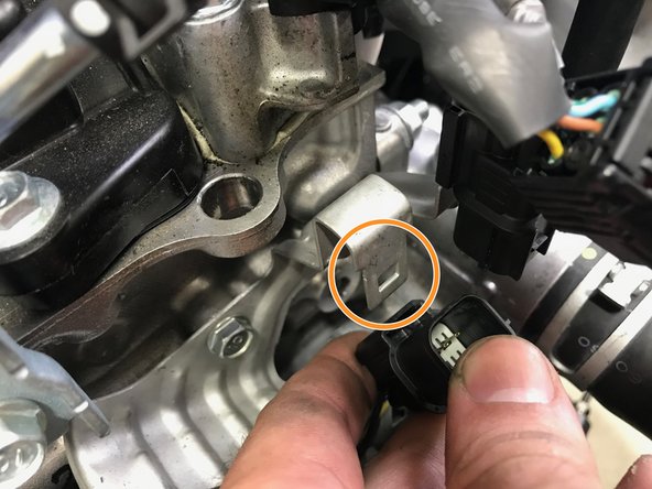
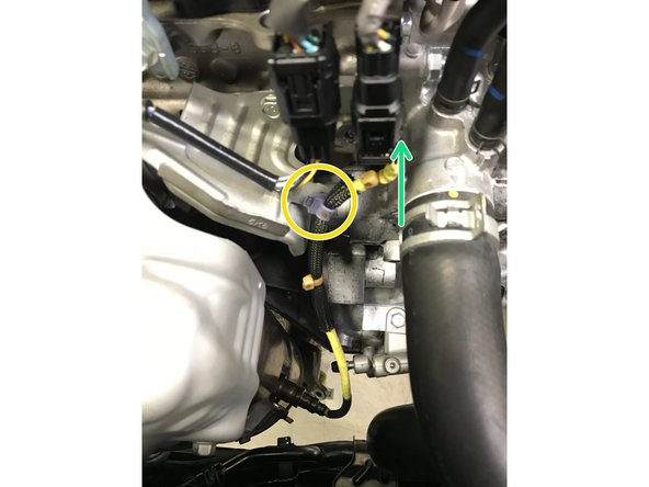
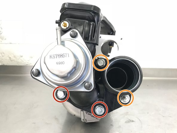
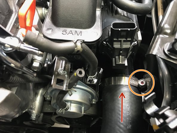
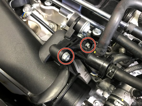
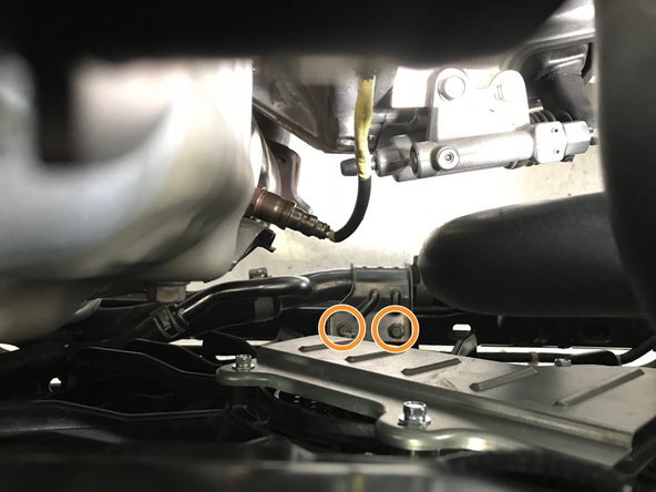
Locating the mounting hardware on the TIP can be difficult. Please see the second image for clear identification
-
The hardware circled in red are bolts. The hardware circled in orange is a nut on a stud
-
Use a 12mm socket, extension & ratchet to loosen the three (3) bolts
-
Use a 13mm socket, extension & ratchet to loosen one (1) nut
-
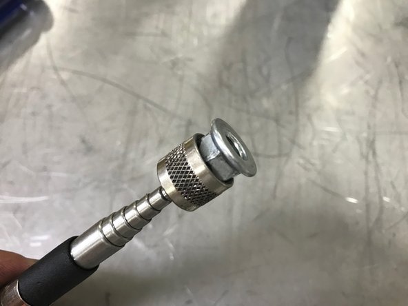
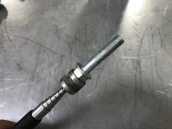
With the bolts loose, but not removed, use the magnet on a stick to remove the bolts from the TIP
-
-
-
Mobile Users proceed to Step 24 for video tutorial
-
Pull the oil dip stick out a couple inches and flex out of way
-
Move the TIP towards the passenger side of the vehicle past the oil dip stick
-
Reinstall the oil dip stick
-
Move the TIP further towards the passenger side of the vehicle and begin to rotate the top of the TIP towards the front of the vehicle
-
Continue the rotation of the TIP while moving the TIP up and out of the engine bay
-
-
-
Pull the oil dip stick out a couple inches and flex out of way
-
Move the TIP towards the passenger side of the vehicle past the oil dip stick
-
Reinstall the oil dip stick
-
Move the TIP further towards the passenger side of the vehicle and begin to rotate the top top of the TIP towards the front of the vehicle
-
Continue the rotation of the TIP while moving the TIP up and out of the engine bay
-
-
-
Verify that the heat shield is not hot. If hot allow the vehicle to cool before proceeding
-
Use a 12mm wrench to remove the three (3) 12mm bolts
-
Remove the heat shield from the engine bay
-
-
-
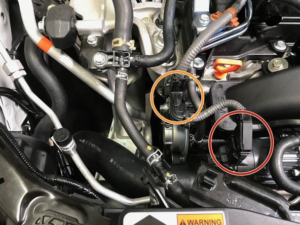
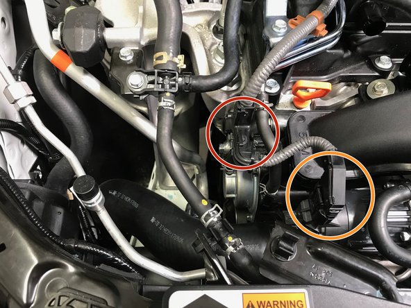
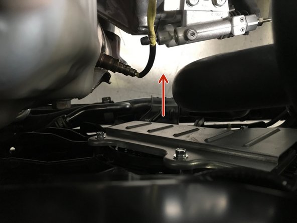
Pull the wire out of the bracket as shown with the red arrow
-
Disconnect the wiring circled in orange
-
Press a tab on the back of the wiring connection and pull down off the bracket as shown in second image
-
Use the O2 sensor socket and ratchet to remove the O2 sensor
-
-
-
Use a 10mm wrench to remove the two (2) 10mm bolts
-
Use a 12mm socket & ratchet to remove the two (2) 12mm bolts
-
Remove the heat shield from the turbo
-
-
-
Locate the wiring bracket to the driver's side of the turbo
-
Use a 10mm socket & ratchet to remove the two (2) 10mm bolts
-
Remove the bracket from the vehicle
-
-
-
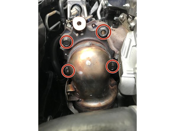
It may be necessary to spray the studs/bolts with a penetrating lubricant before removal. Apply lubricant if needed and let sit for a few minutes then attempt removal
-
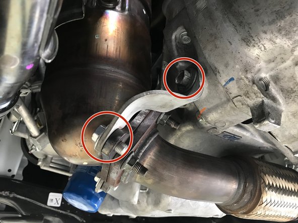
Use a 17mm socket & ratchet to remove the two (2) nuts and two (2) bolts
-
Move the downpipe off the studs towards the driver's side
-
Lower the downpipe straight down through the opening below
-
-
-
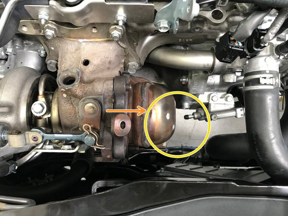
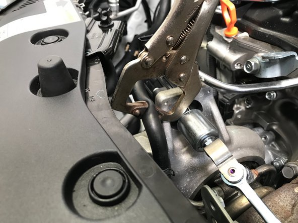
Vise grips/clamps can damage the hose if they set too tight. Setup the vise grips/clamp to squeeze the hose just enough to keep the coolant from leaking
-
Use small vise grips/clamp to pinch the upper coolant hose on the turbo in the area indicated by the red arrows
-
-
-
Use a 10mm socket & ratchet to remove the two (2) 10mm bolts that attach the oil drain tube to the bottom of the turbo, set the bolts aside as they will not be reused.
-
There is a small black metal gasket between the oil drain tube and the turbo. Do not loose or damage it, it will be reused
-
Use pliers to loosen the spring clamp. Slide the spring clamp down the rubber hose
-
Remove the oil drain tube from the vehicle
-
A small amount of oil may spill out of the drain tube upon removal
-
-
-
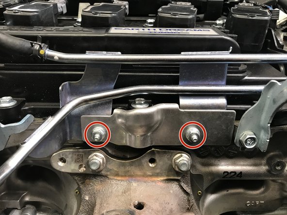
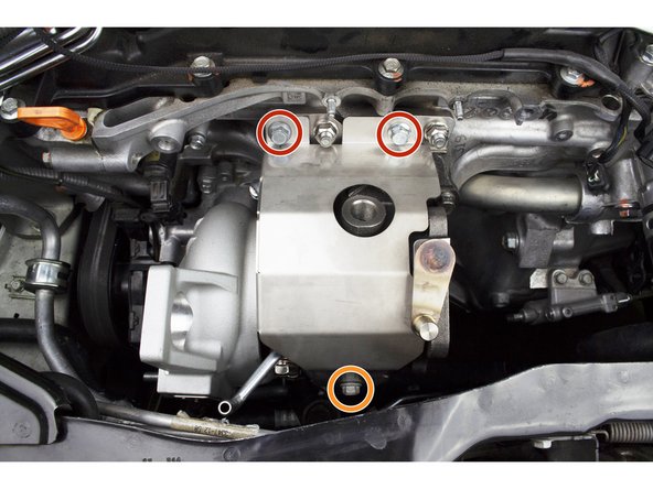
Use a 14mm socket & ratchet to remove the two (2) 14mm bolts holding the turbo support bracket
-
The two bolts are different lengths. The long bolt is used on the turbo and the short block is used on the engine block
-
-
-
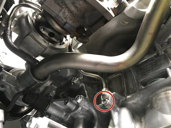
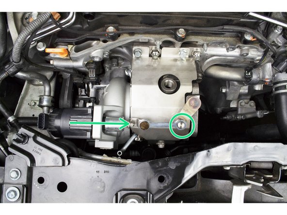
Use a 10mm socket & ratchet to remove the one (1) 10mm bolt holding the lower portion of the oil feed tube
-
A small amount of oil may spill out of the oil feed tube upon removal
-
-
-
Vise grips/clamps can damage the hose if they are too tight. Setup the vise grips/clamp to squeeze the hose just enough to keep the coolant from leaking
-
Use small vise grips/clamp to pinch the lower coolant hose on the turbo in the area shown with red arrows
-
Use pliers to loosen the spring clamp. Slide the spring clamp towards the center of the rubber hose
-
Pull the rubber hose off the turbo coolant tube
-
Some coolant will spill out of the turbo and rubber hose upon removal
-
-
-
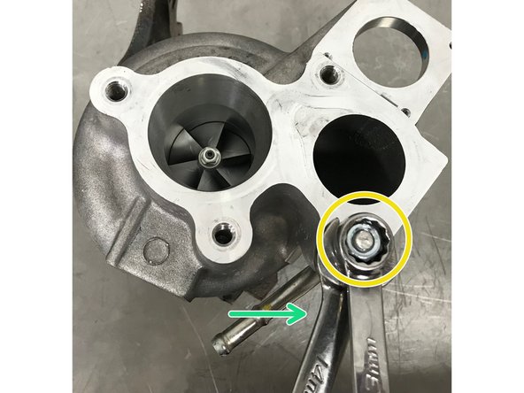
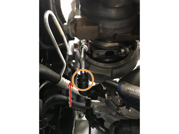
Use a 12mm socket, extension, & ratchet to remove the oil feed banjo bolt
-
Remove the entire oil feed tube and banjo bolt for the turbo
-
-
-
Use pliers to loosen the spring clamp. Slide the spring clamp up the rubber hose
-
Pull the rubber hose off the turbo tube
-
More coolant will spill out of the lower turbo coolant tube
-
-
-
Use a 10mm socket & ratchet to remove two (2) 10mm nuts holding the bracket
-
Use a flat head screwdriver to open the plastic clip holding the rearward coolant hose, as shown in the third image
-
Lift the whole assembly up and set it on the valve cover out of the way
-
-
-
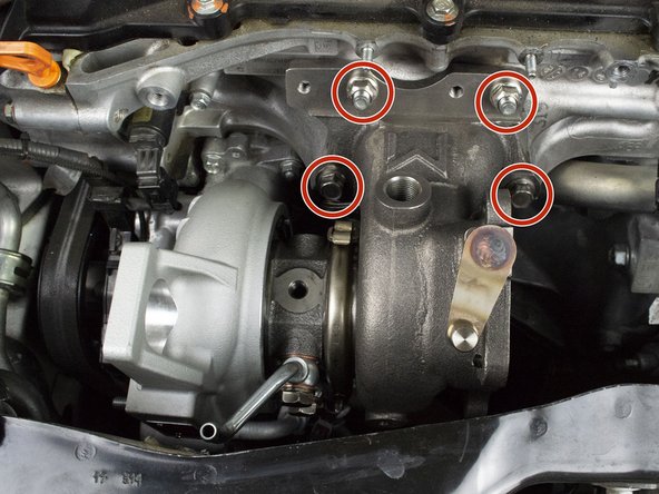
Use a 14mm socket, extension, & ratchet to remove the two (2) nuts and two (2) bolts holding the turbo to the engine
-
These nuts and bolts will be reused for installation
-
-
-
Mobile Users please proceed to the next step for a video tutorial
-
Pull the turbo off the studs in the engine block
-
Move the turbo slightly towards the passenger side of the vehicle
-
Raise the compressor side of the turbo up first then remove the whole turbo from the engine bay
-
-
-
Pull the turbo off the studs in the engine block
-
Move the turbo slightly towards the passenger side of the vehicle
-
Raise the compressor side of the turbo up first then remove the whole turbo from the engine bay
-
-
-
Carefully pry the 9 plastic clips open with a flat head screw driver
-
Clips are fragile and can easily break if to much force is applied
-
-
-
Relocating your hood prop is necessary to run the W2 and W3 turbo, failure to do so will result in damage to your WGA
-
Use needle nose pliers to squeeze the clip on the bottom of the hood bracket to remove the plastic clip. Set aside for reuse later
-
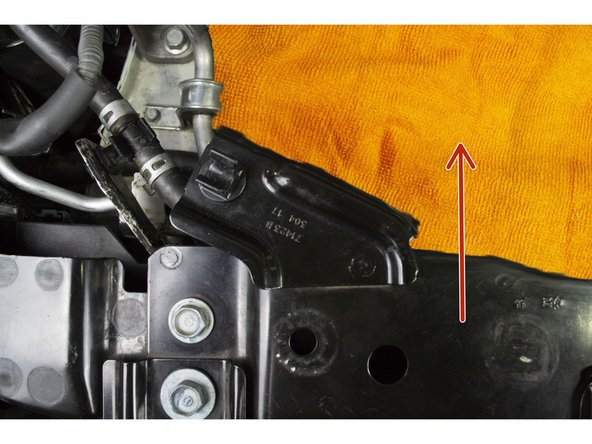
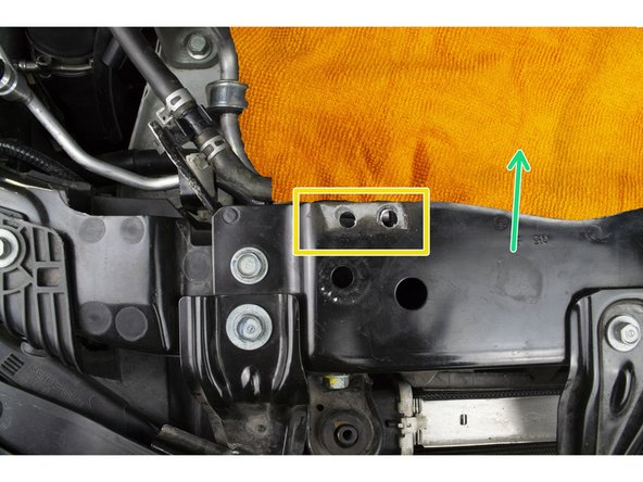
When drilling in the next step be mindful to not hit the coolant line that is clipped below, Unclip the coolant line and make sure it is out of the way
-
Cover up the engine, coolant system, and oil system before starting to drill (a big old towel would work good for this).
-
A vacuum is recommended to clean up metal chips
-
-
-
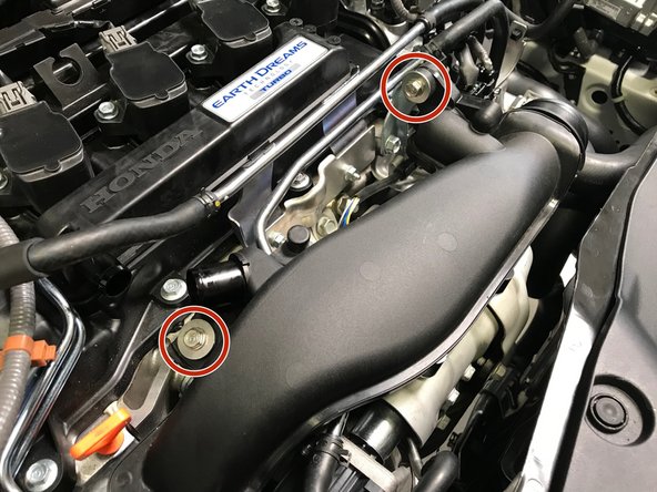
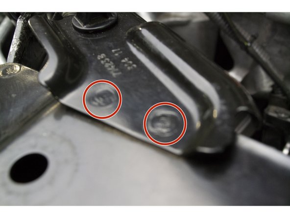
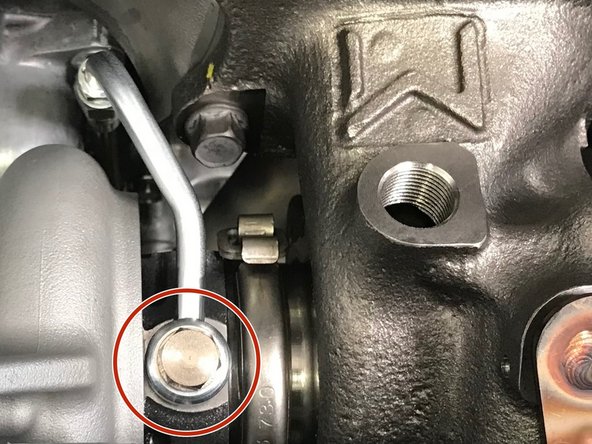
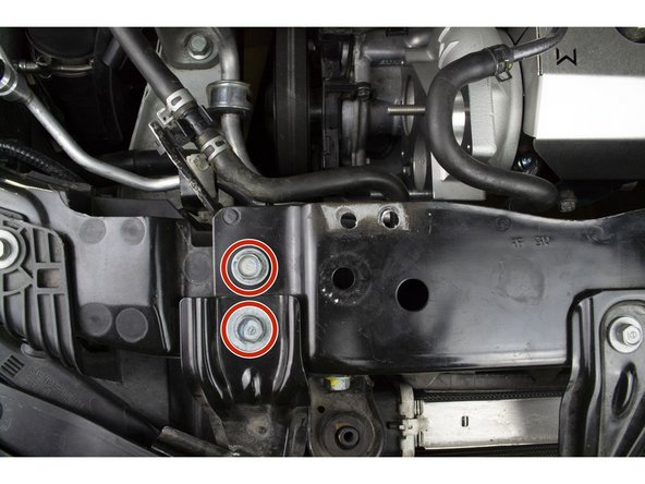
Use a 1/4" drill bit to drill out the 2 tac welds circled in red
-
If the bracket is still attached after drilling both welds then you can fatigue the bracket loose by bending it up and down a few times or try drilling the hole with a 5/16" drill bit
-
When done drilling cleanup all metal chips before removing towel, a shop vaccum is recommended for cleaning this up
-
When all metal chips have been cleaned up then you can remove the towel
-
Two (2) M6x20mm bolts and nuts are provided in case you wish to reinstall the hood prop
-
-
-
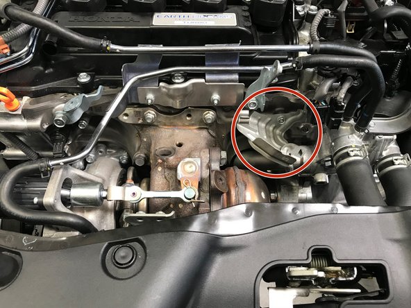
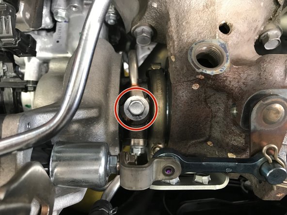
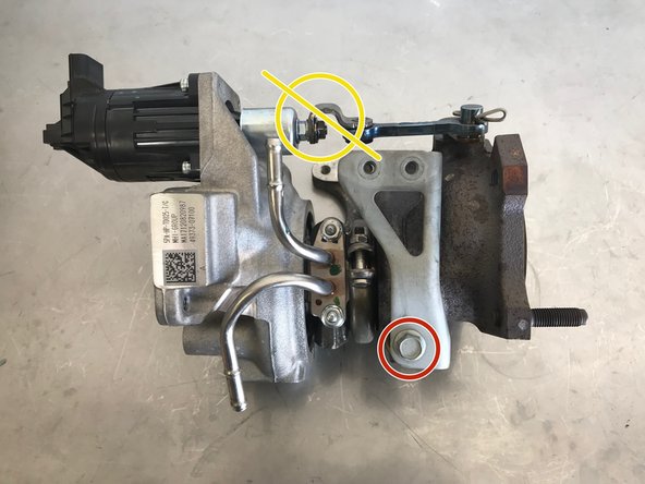
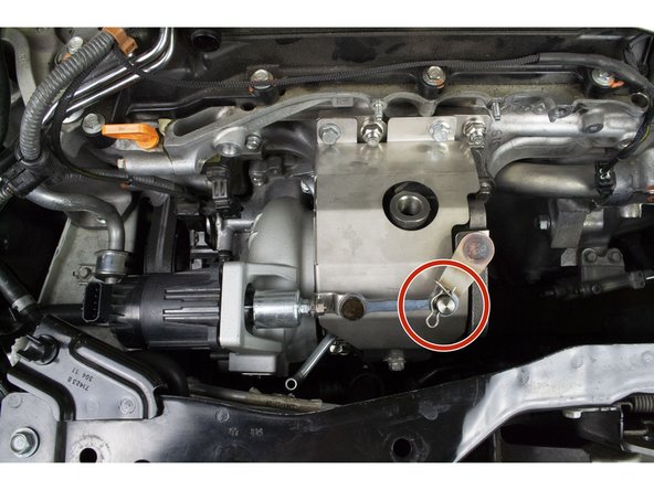
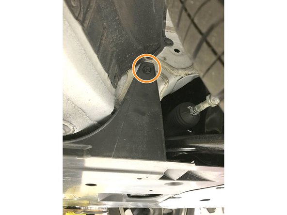
Use a 12mm wrench to remove the bolt holding the bracket shown
-
Set aside bracket and bolt as they will not be reused for installation
-
Do not touch this jam nut during this install
-
-
-
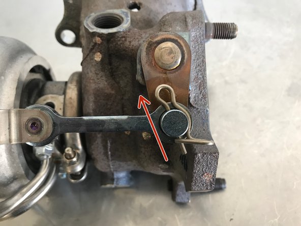
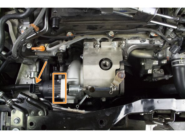
Remove the cotter pin from the turbo
-
This can fly off unexpectedly if not careful
-
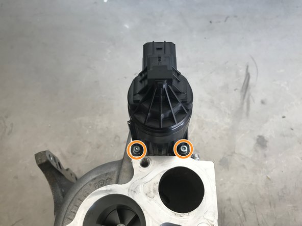
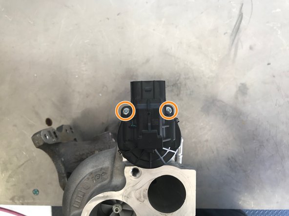
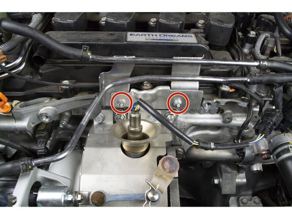
Use a 3mm Allen to remove the four (4) socket caps screws holding the WGA
-
Remove the WGA from the OE turbo
-
-
-
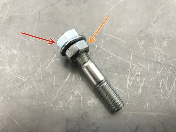
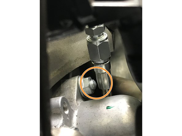
Thread on the provided M8x1.25 nut onto the OEM stud in your OEM turbo, this is shown off the turbo for clarity
-
Thread on the OE flange jam nut onto the turbo stud on top of the M8 nut, this is shown off the turbo for clarity
-
Use a 13mm and 12mm wrench to tighten the two nuts into each other
-
Using the wrench on the lower nut, "un-thread" the nut. This should begin un-threading the stud from the OE compressor housing
-
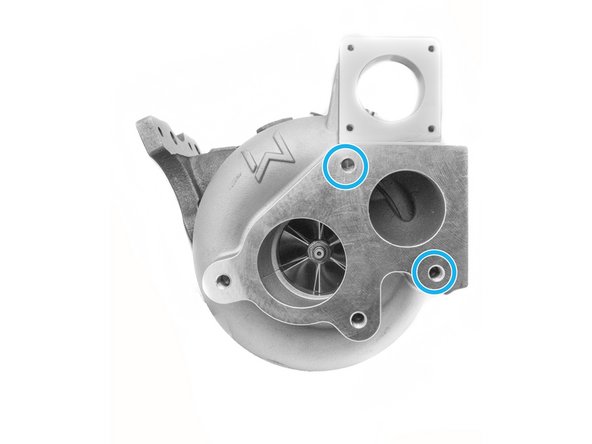
Repeat this process in reverse to install the OE stud you just removed as well as the provided M8x35mm double ended stud into your turbo at holes circled in blue
-
-
-
Locate the provided Upper Coolant Pipe, M14 Banjo Bolt, and two (2) M14 Copper Crush Washers
-
Upper Coolant Pipe
-
M14 Coolant Banjo Bolt
-
M14 Copper Crush Washers
-
-
-
Assemble the upper coolant pipe as shown. There should be one crush washer on each side of the coolant pipe bolt connection
-
Install the upper coolant pipe on the turbo as shown. Torque to 32-36 ft-lbs
-
Warning improper connection or failure to follow torque specs could cause a coolant leak
-
-
-
Locate the provided Lower Coolant Pipe, M14 Banjo Bolt, and two (2) M14 Copper Crush Washers
-
Lower Coolant Pipe
-
M14 Coolant Banjo Bolt
-
M14 Copper Crush Washers
-
-
-
W2 & W3 come with the heat shield installed. It will need to be removed now
-
Remove the three bolts attaching the heat shield to the turbine housing using a 13mm socket
-
Set aside heat shield or now
-
-
-
Assemble the lower coolant pipe as shown. There should be one crush washer on each side of the coolant pipe bolt connection
-
Install the lower coolant pipe on the turbo as shown. Torque to 32-36 ft-lbs
-
Warning improper connection or failure to follow torque specs could cause a coolant leak
-
-
-
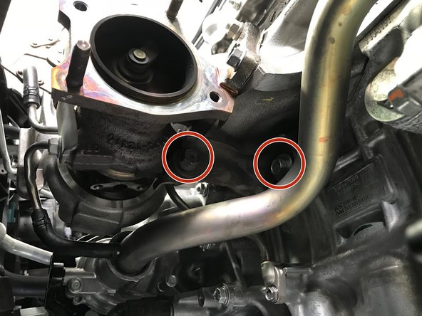
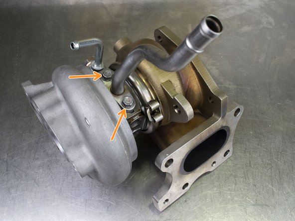
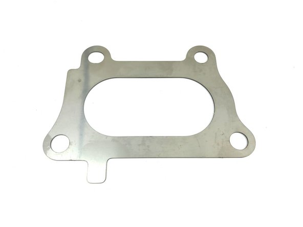
Locate the OE oil drain pipe and OE oil drain pipe gasket
-
Align the drain pipe flange and gasket with the holes on the underside of the turbo. Use a 10mm socket and torque wrench. Torque the two (2) provided M6 12mm long flanged bolts to 8-10 ft-lbs
-
-
-
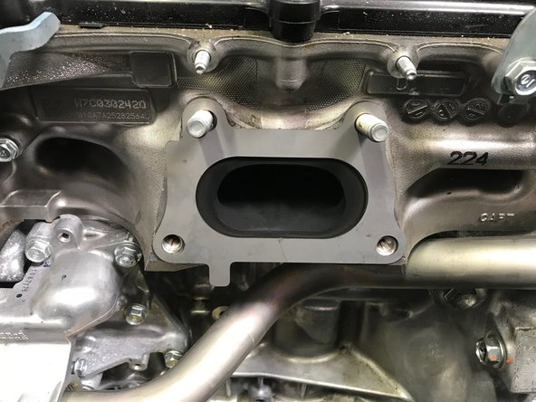
Locate the provided turbine inlet gasket and install as shown
-
-
-
Install the Turbo onto the engine as shown in the reverse order of removal.
-
Use a 14mm socket and torque nuts and bolts to 42-48 ft-lbs
-
-
-
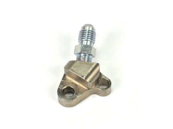
Locate the provided oil feed block fitting
-
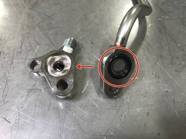
Locate the OE oil feed tube. Use a small flat head screwdriver to remove the O-ring/screen from the OE oil feed tube
-
Be careful to not damage the O-ring during removal and installation
-
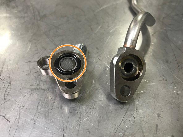
Install the O-ring/screen into the oil feed block fitting as shown
-
-
-
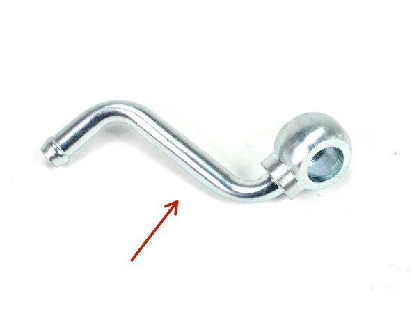
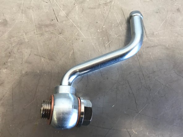
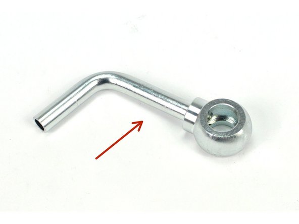
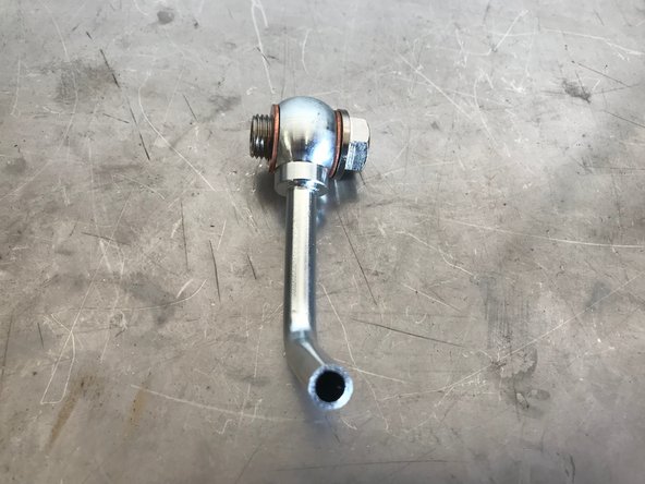
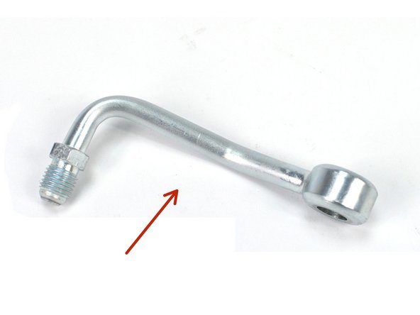
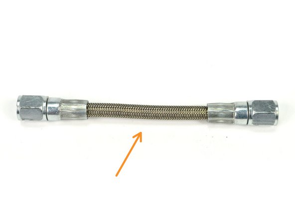
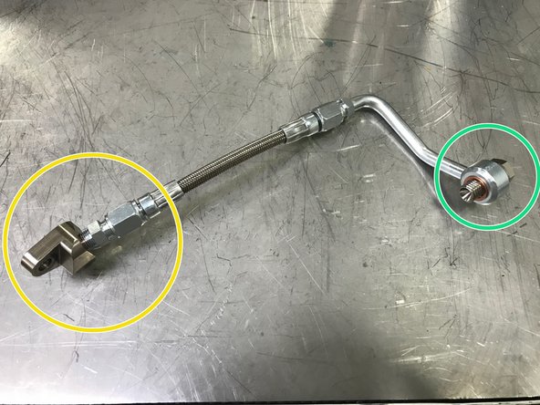
Locate the provided oil feed pipe and oil feed braided hose
-
Oil Feed Pipe
-
Oil Feed Braided Hose
-
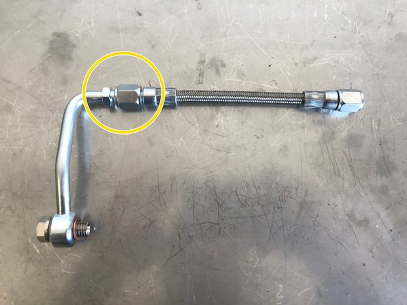
Attach the oil feed pipe and oil feed braided hose
-
Use a 12mm and 14mm wrench to tighten the pipe and hose. Hand tighten then use wrenches to tighten an extra 1/8 - 1/4 turn
-
-
-
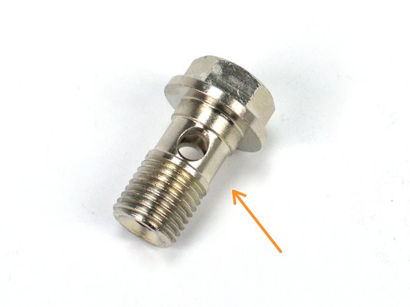
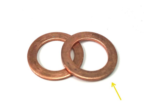
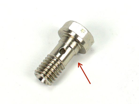
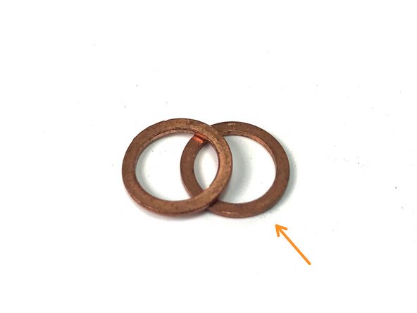
Locate the provided oil feed banjo bolt and two (2) M10 copper crush washers
-
M10 Oil Feed Banjo Bolt
-
M10 Copper Crush washers
-
Install the oil feed block fitting that has the O-ring screen installed. Hand tighten the oil feed block fitting, do not fully tighten yet
-
Install the oil feed banjo bolt and crush washers as shown. There should be one crush washer on each side of the oil feed bolt connection
-
-
-
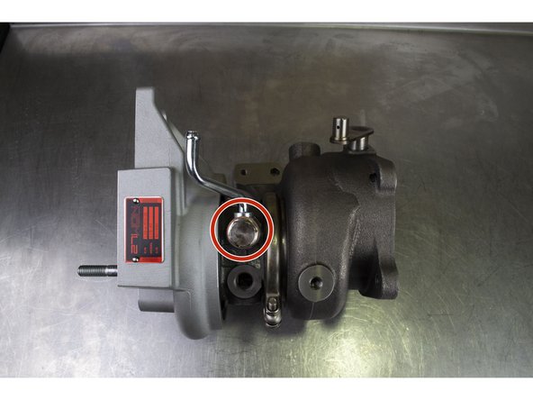
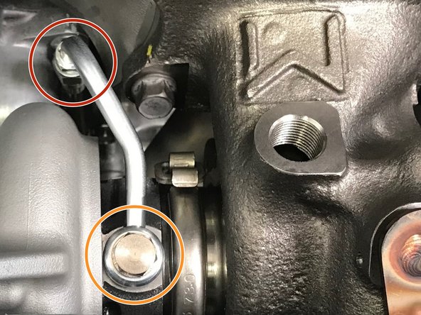
Install the assembled oil feed line onto the turbo
-
Route the oil feed block fitting and braided hose as shown
-
Hand tighten the oil feed banjo bolt into the turbo as shown
-
Verify that the upper and lower copper crush washers are on the oil feed banjo bolt
-
-
-
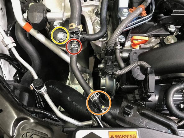
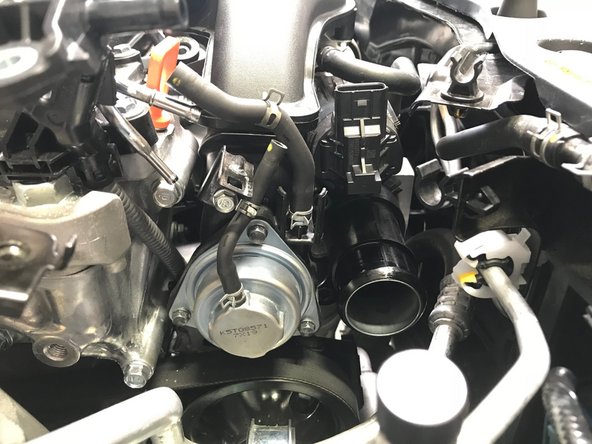
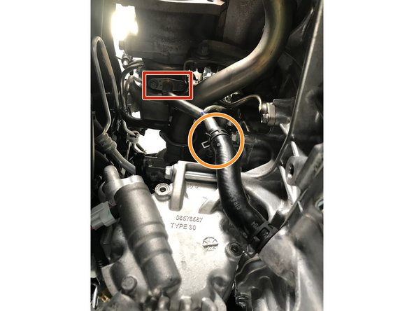
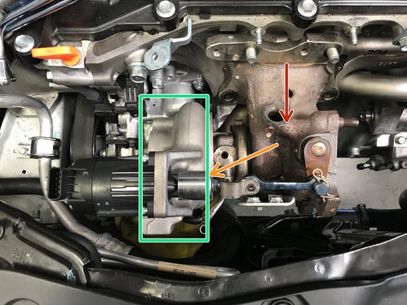
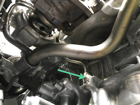
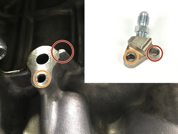
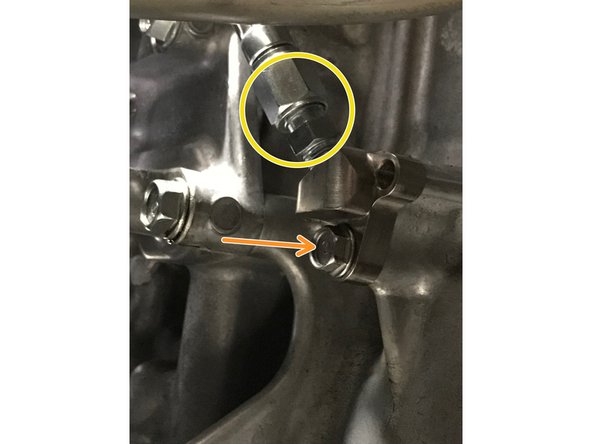
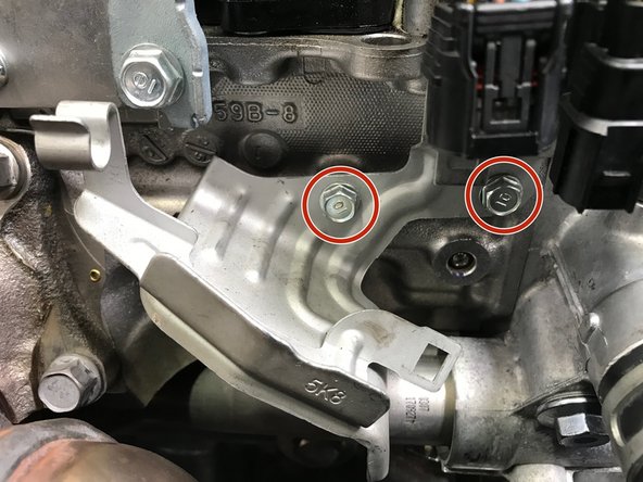
Locate the oil feed block connection location shown in the first image, you removed the oil drain line from it earlier
-
The small protrusion on the engine is critical and must align with the hole on the side of the oil feed block fitting circled in red
-
Insert the fitting block onto the protrusion (red circle to red circle) and then align the hole on the block fitting with the hole in the engine (orange circle to orange circle), then install the OE 10mm bolt. Torque to 9-11 ft-lbs
-
Use a 12mm and 14mm wrench to tighten the block fitting and hose. Hand tighten then use wrenches to tighten an extra 1/8 - 1/4 turn
-
-
-
Use a 14mm socket and torque the oil feed banjo bolt to 12-14 ft-lbs
-
Verify that the oil feed braided hose is not touching or rubbing any components. If touching is occurring loosen the oil feed banjo bolt and adjust the position
-
-
-
Use pliers to remove the remaining spring clamp on the OE lower rubber coolant hose that is not installed on the engine currently. Install the spring clamp on the provided rubber coolant hose that is installed on the engine currently
-
Push the coolant hose onto the lower coolant pipe
-
Use pliers to install the spring clamp at the end of the hose over the coolant pipe
-
Do NOT remove the vise grips yet, or coolant will spill out of the turbo upper coolant pipe
-
-
-
Install the LONG 14mm bolt through the bracket into the turbo
-
Install the SHORT 14mm bolt through the bracket into the engine
-
Use a 14mm socket and torque wrench. Torque each to 38-42 ft-lbs
-
-
-
Use pliers to install the spring clamp at the end of the rubber hose around the oil drain pipe
-
-
-
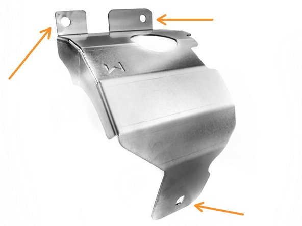
Use a 13mm socket & torque wrench to install two (2) provided M8x10mm bolts and torque to 15-18 ft-lbs
-
Use a 13mm socket & torque wrench to install one (1) provided M8x8mm bolt and torque to 15-18 ft-lbs
-
You may need to flex the heat shield a bit to align the mounting holes
-
-
-
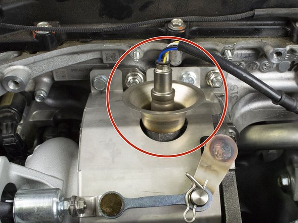
Install the WGA through the compressor housing and attach the WGA rod to the waste gate arm
-
Install the cotter pin
-
Verify that the WGA wiring connection is pointed up. Install the four (4) 3mm Allen socket cap screw and tighten to snug.
-
Do not over-tighten the 3mm Allen screws. Hand snug is sufficient
-
-
-
Use the specialty O2 sensor socket to install the primary O2 sensor. Torque to 30-33 ft-lbs
-
-
-
Install the upper coolant hard lines support bracket and shield that was removed. Use a 10mm socket & torque wrench to install the two (2) 10mm nuts and torque to 8-10 ft-lbs
-
Push the rubber coolant hose onto the turbo upper coolant pipe
-
Use pliers to install the spring clamp at the end of the coolant hose around the upper coolant pipe
-
-
-
Reinstall the plastic clip holding the upper coolant hard lines and rubber hose
-
-
-
Remove the vise grips from the lower coolant hose
-
-
-
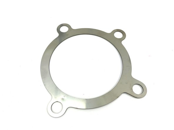
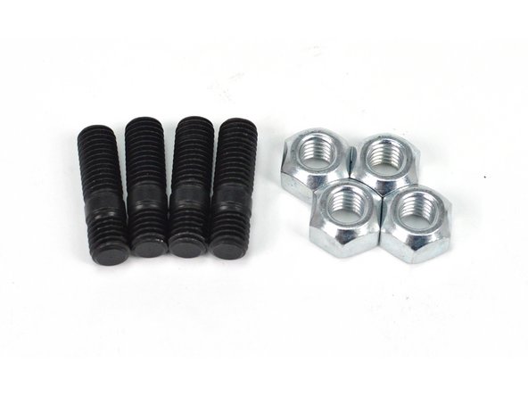
Locate the provided turbine outlet gasket, four (4) M10 studs, and four (4) M10 crimp nuts
-
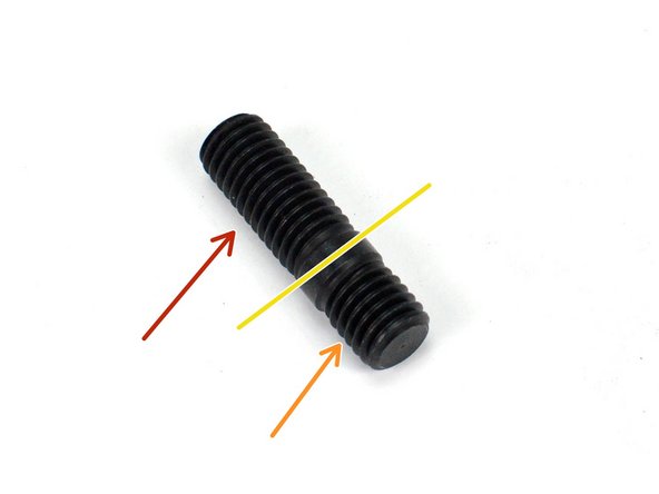
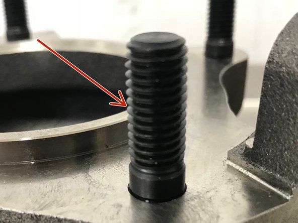
The provided M10 studs have a short thread section and a long threaded section
-
The short section of threads will be threaded into the turbo
-
The long section of threads protrudes out of the turbo to support the downpipe
-
-
-
By hand, install the four (4) M10 studs into the turbo with the long section out
-
This step shown on bench for clarity
-
Install the turbine outlet gasket. There is only way it can be installed
-
Use a 17mm socket & torque wrench to install the four (4) M10 crimp nuts. Torque to 42-48 ft-lbs
-
-
-
Use a 10mm socket & torque wrench to install the two (2) 10mm bolts and bracket. Torque to 8-10 ft-lbs
-
-
-
Use a 12mm wrench to install the three (3) 10mm OEM bolts and heat shield. Torque to 15-19 ft-lbs
-
Some aftermarket downpipes may not have the provision for this heat shield
-
-
-
Use the specialty O2 sensor socket to install the secondary O2 sensor. Torque to 30-33 ft-lbs
-
-
-
Install the secondary O2 sensor wiring harness onto the bracket
-
Install the primary O2 sensor wiring harness onto the bracket
-
-
-
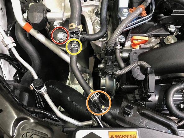
Install the primary wire into the metal clip
-
Connect the primary sensor to the wiring harness as indicated by orange arrow
-
Install the purple clip on the secondary wire into the bracket
-
Connect the secondary sensor to the wiring harness as indicated by green arrow
-
-
-
Installation of the TIP follows the same process for removal in reverse
-
Lower the TIP into the engine bay with the TIP rotated towards the front of the car
-
Rotate and lower the TIP into the engine bay then move it towards the driver's side of the engine bay
-
Pull the oil dip stick out a couple inches and flex out of way
-
Move the TIP further to the driver's side while sliding the TIP over the stud in the compressor housing
-
Reinstall the oil dip stick
-
-
-
With the TIP loosely in position on the turbo, we will begin the most frustrating part of the entire installation
-
Using the Magnet on a Stick we can loosely thread the nut onto the stud and the bolts into the compressor housing without the risk of loosing the hardware in the engine bay
-
-
-
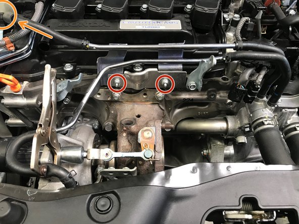
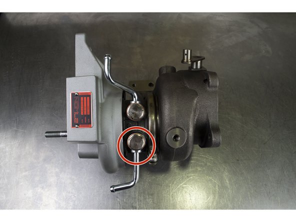
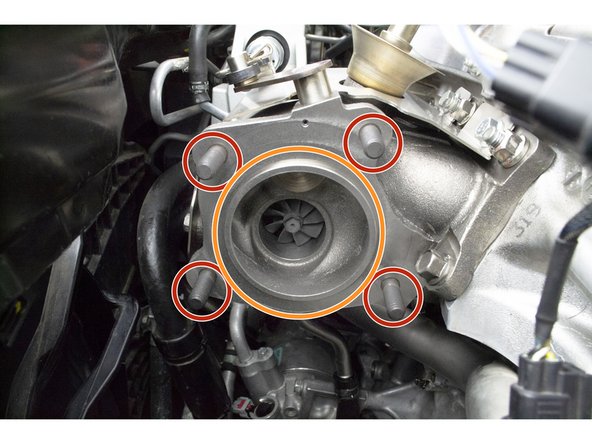
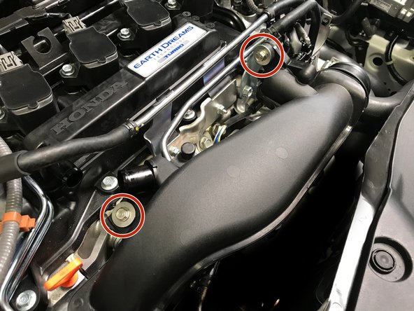
An installed TIP is shown out of the car for clarity
-
The two (2) red circles show the locations of the 12mm bolts
-
The orange circle shows the location of the two (2) 13 mm nuts and studs
-
Use the magnet on a stick tech tip shown earlier to first loosely install the bolts and nut
-
Tighten the hardware and torque to 15-19 ft-lbs
-
-
-
Use a 10mm socket & torque wrench to install the two (2) TIP mounting bolts. Torque to 8-10 ft-lbs
-
-
-
Pull the hose out and reinstall the band clamp in the same orientation it came off
-
Push the hose onto the TIP in the direction of the arrow
-
Use a 10mm socket & ratchet or Phillips screwdriver to tighten the worm-gear clamp until snug
-
-
-
Use a 10mm socket to install the bolt holding the "T" connection. Torque to 8-10 ft-lbs
-
Pop the hose into the plastic clip
-
Push the hose onto the plastic "T". Use pliers to install the spring clamp at the end of the coolant hose around the "T" connection
-
-
-
Push the BPV hoses onto the metal tubes in the direction of the red arrows
-
Use pliers to install the spring clamps onto the end of the hoses around the metal pipe
-
-
-
Install the wiring harness back onto the bracket
-
Reconnect the wiring harness to the WGA
-
-
-
Push the hose onto the TIP first, following the red arrow.
-
Push the hose onto the valve cover second
-
Use pliers to install the spring clamps onto the end of the hose
-
-
-
Use a 10mm socket & torque wrench to install the two (2) 10mm bolts. Torque to 8-10 ft-lbs
-
-
-
Move the radiator hose back into the correct position so the bolt holes and bracket holes align
-
Use a 10mm socket & torque wrench to install the two (2) 10mm bolts holding the lower radiator hose in place. Torque to 8-10 ft-lbs
-
-
-
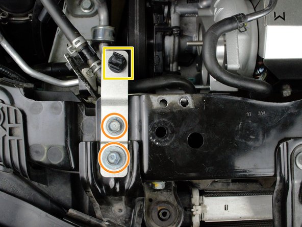
With a 12mm socket wrench remove the two (2) 12mm bolts
-
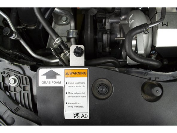
Locate the plastic hood prop clip from earlier and insert it into the square hole on the new hood prop bracket
-
You should hear a click when the hood prop clip is fully inserted, if you don't hear a click then you can insert your needle nose pliers between the clip prongs to bend them out to the locked position
-
Install the new hood prop bracket and reinstall the two (2) 12mm bolts, torque to 8-10 ft-lb
-
-
-
Reinstall radiator fan guard by inserting the 9 plastic clips and pressing down on them with your thumb
-
-
-
Use a 14mm socket or wrench to install the four (4) 14mm bolts and brackets. Torque to 38-42 ft-lbs
-
-
-
Use a 14mm socket & torque wrench to install the three (3) 14mm nuts/studs. Torque to 30-40 ft-lbs
-
-
-
Apply a small amount of silicone spray to the end of the hanger rod
-
Push the rubber hanger onto the hanger rod
-
-
-
Lower the airbox assembly into the engine bay
-
Install the induction hose onto the TIP
-
Use a 10mm socket and torque wrench to install the two (2) 10mm bolts that hold the airbox assembly. Torque to 3-4 ft-lbs
-
Use a 5.5mm socket or phillps screwdriver to tighten the band clamp until snug
-
Install the wiring harness into the airbox
-
Reconnect the MAF sensor wiring
-
-
-
Using genuine Honda coolant, fill the coolant reservoir to MAX
-
Leave the cap off the coolant reservoir for first start and engine warm up
-
For the first engine start be on alert for any oil and coolant leaks. It is recommend to have a second person watching the engine bay for leaks on first start
-
Start the engine and inspect for leaks. Shut down immediately is a leak is found. Fix any leaks found
-
Some smell and faint smoke will be present on first start-up. This is normal and will not happen after the 2nd or 3rd heat cycle
-
-
-
Install the seventeen (17) plastic push-clips. Orange arrows identify the push-clips described in the next step
-
Use 10mm socket & torque wrench to install the seven (7) bolts shown in red circles. Torque to 8-10 ft-lbs
-
Use 5mm Allen and torque wrench to install the two (2) bolts shown in green circles. Torque to 8-10 ft-lbs
-
-
-
Install the remaning six (6) push-clips on each side of the skidtray
-
-
-
Check the engine coolant level in the reservoir for the next few days as the air in the cooling system works itself out. Refill as needed
-
Some smell and faint smoke will be present on first start-up. This is normal and will not happen after the 2nd or 3rd heat cycle
-
To get the best performance from your W2/W3 Turbo, we highly recommend a custom tune
-
A custom tune for your specific vehicle with your specific modifications will provide the best performance for your Civic and the location you live in
-
Please see the next step for expectations for driving a performance turbo equipped vehicle
-
An upgraded clutch is required for peak performance use of the W2/W3 turbocharger
-
-
-
A vehicle equipped with a larger performance turbocharger may require a change in the way it is driven to get the full effect of it
-
A properly tuned vehicle with a larger turbocharger will experience peak torque later in the RPM range. This may make the vehicle feel more sluggish in the the lower RPM range, approximately sub 3000rpm. However, peak power will also move higher in the RPM range and carry to redline
-
We recommend shifting at a higher RPM to combat this feeling
-
W2: ~300rpm higher
-
W3: ~800rpm higher
-
A larger performance turbocharger will also create more pronounced turbo induction noises, your gas mileage may drop significantly for the first few tanks from you constantly wanting to hear the turbo spool
-
-
-
If at anytime you wish to remove your 27WON turbo and reinstall you OEM hood prop then this can be done using the provided hardware
-
Insert the two provided M6x 20mm bolts through the bracket and the radiator support. Thread the two provided M6 nuts onto the other end of the bolts
-
Place a 10mm wrench on the nut and a 10mm socket and ratchet on the bolt and torque the bolt to 8-10 Lb-ft
-
-
-
This completes the installation of your 27WON W2/W3 Performance Drop-In Turbo Kit
-
We hope you were impressed with your 27WON experience and love your new W2 Turbo for years to come. Email us at sales@27won.com or call us at 571-271-0271 with any questions or concerns
-
Please Leave a review here:
-
-
-
Share your experience using #27WON on Instagram and Facebook
-