Introduction
In this installation guide we have provided step by step instructions to remove the OEM Turbo Inlet Pipe (TIP) and install the 27WON TIP on a 2022 Civic EX. Other 2022+ Civic and Integra 1.5T models will be similar
- The exhaust piping, turbocharger, and cooling system will be hot after recent vehicle operation. Allow the vehicle to cool or use a fan to cool the exhaust components before working on the vehicle.
Tools
- Torque Wrench (3/8" Drive)
- 1/4" Ratchet
- 3/8" Ratchet
- 3" Extension (1/4" Drive)
- 12mm Socket
- 10mm Socket
- 8mm Socket
- 5.5mm Socket
- T30 Torx Socket
- Phillips Screwdriver
- Flathead Screwdriver
- 90 Degree Pick Tool
- Wire Cutters
- Vice Grip Pliers
- Pliers - Large
- 3mm Allen key
- Dremel w/Cutting Disc
- Heat Gun
- Electrical Tape
- Optional: Push Clip Removal Tool
- Optional: Hose Pliers
- Optional: Riv-Nut Tool
Parts
- 27Won Turbo Inlet
- Turbo Inlet Pipe Gasket
- EVAP Valve Gasket
- T-Bolt Clamp - 95-103mm
- T-Bolt Clamp - 73-81mm
- T-Bolt Clamp - 70-78mm
- T-Bolt Clamp - 32-37mm
- Worm Gear Clamp 11-20mm
- Spring Clamp - 11mm × 4
- Spring Clamp - 13mm × 2
- Wiring Loom T-Cover
- Vacuum Shrink Wrap Tubing - 2in Length
- M5x0.8x12mm SS Riv Nut × 6
- M5 Flat Washers × 6
- M5 Cap Screw × 6
- M5x0.8x8mm Flanged Bolt × 2
- 4mm Black Silicone Hose - 9in Length
- 5.5mm Black Silicone Hose - 5in Length
-
-
First and foremost; THANK YOU for becoming a part of the 27WON Family. We hope to REDEFINE your experience of the aftermarket with the highest level Parts, Customer Service, Packaging, & Support
-
You will proceed to remove the OEM Turbo Inlet Pipe (TIP) from the vehicle in the coming steps
-
These instructions are for OE intake. Other intakes will be similar
-
-
-
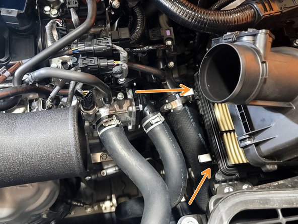
Use a 5.5mm socket and 1/4" ratchet to remove the two (2) clamps (red markups) securing the accordion style intake air tube
-
Remove intake air tube from car and set aside
-
-
-
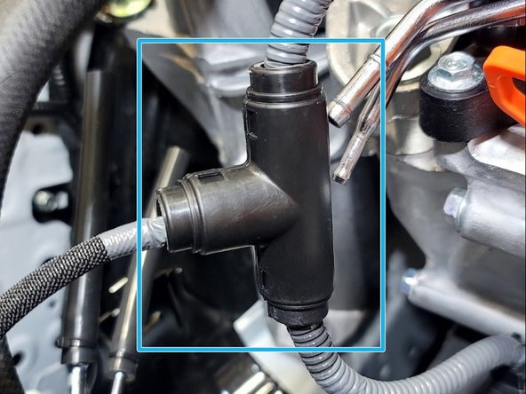
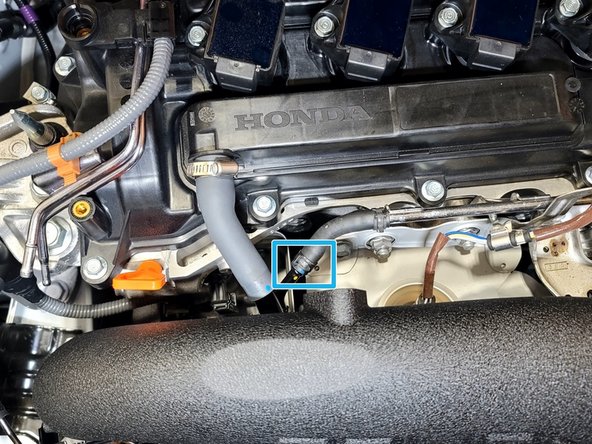
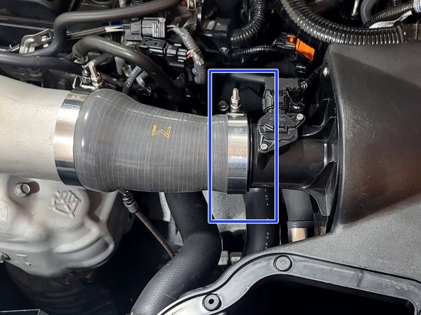
Remove two (2) screws from Turbo Inlet Pipe (TIP) EVAP valve with T30 Torx Bit
-
Pop both EVAP lines from clip
-
Tuck EVAP valve out of the way as shown (blue box)
-
-
-
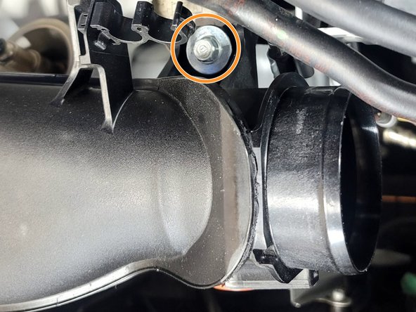
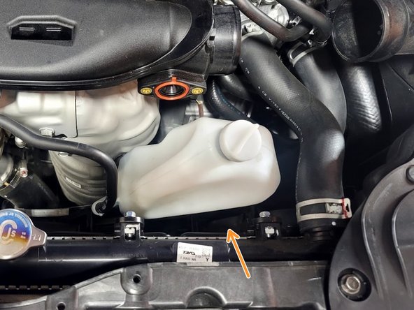
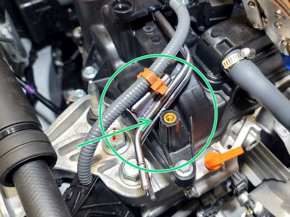
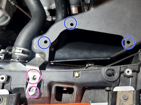
Use 10mm socket and ratchet to remove bolt from TIP bracket near inlet
-
-
-
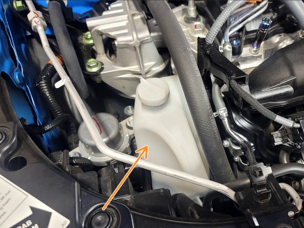
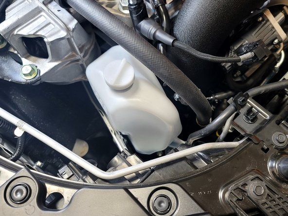
Pull up on reservoir to free from bracket and relocate as shown
-
-
-
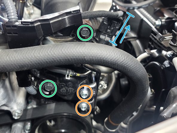
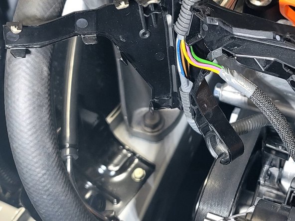
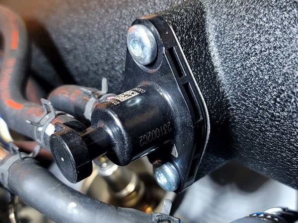
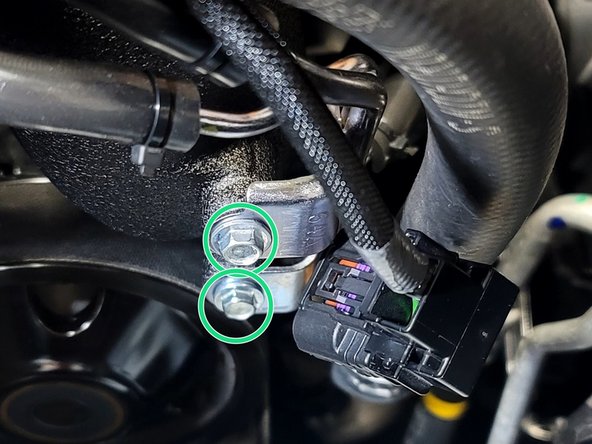
Use 10mm socket and ratchet to remove two (2) bolts from vacuum bracket
-
Use 10mm socket and ratchet to remove two (2) bolts from wiring loom cover
-
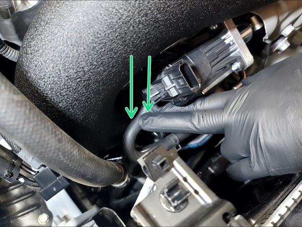
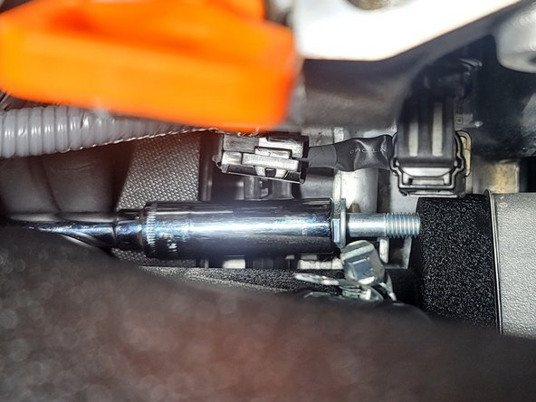
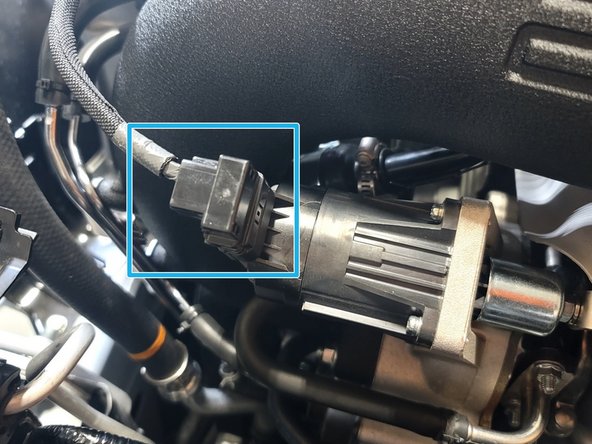
Unplug waste gate actuator by pushing the very top of the clip in with one finger and pulling the plug out with the other hand
-
Set wiring loom out of the way
-
-
-
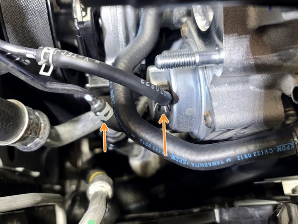
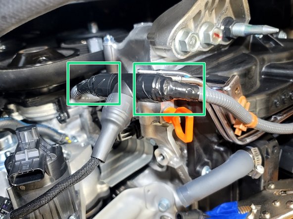
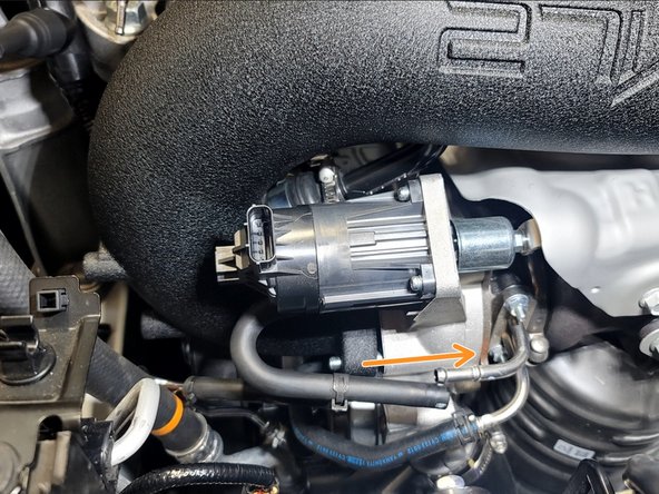
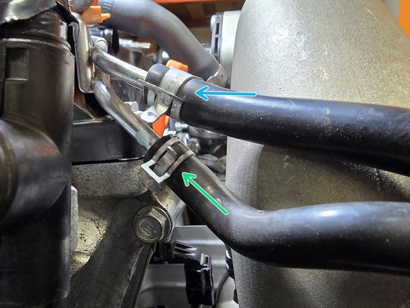
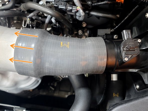
Use pliers to slide the two (2) hose clamps down the rubber hose
-
Twist each hose to break adhesion to metal tube then and pull both hoses off
-
Use hose pliers if you have them, it's easier
-
Use caution to avoid tearing rubber but it can take some force to free hoses
-
Set hoses out of the way
-
-
-
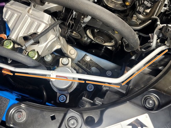
Use caution not to bend or damage A/C line while removing TIP
-
Be careful not to damage A/C line
-
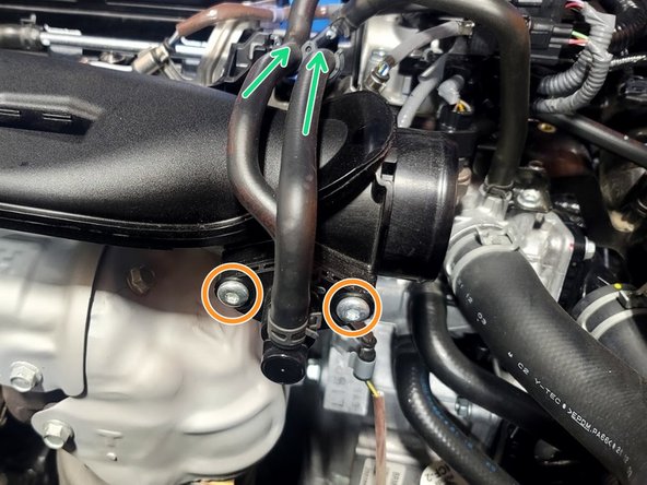
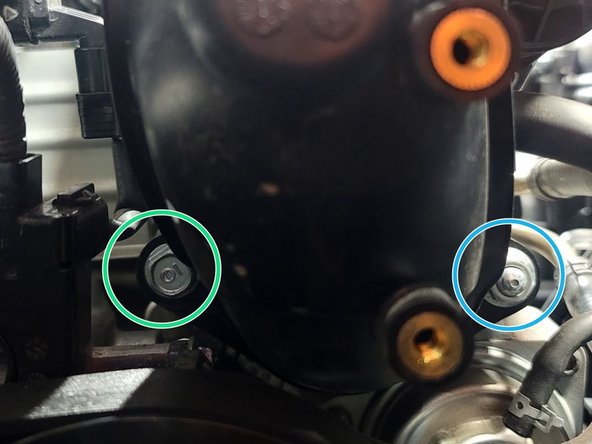
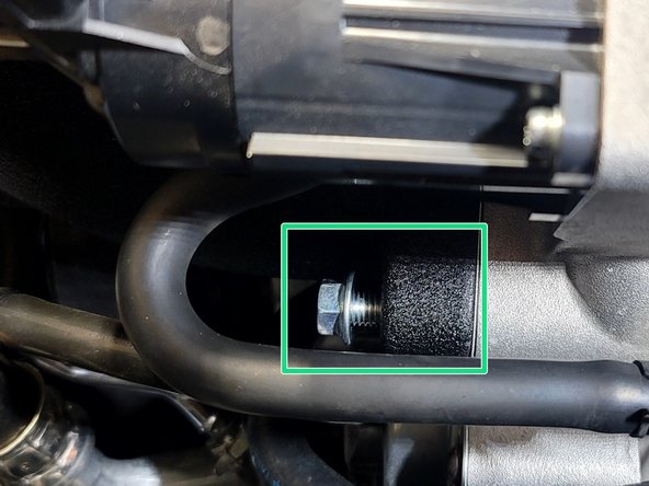
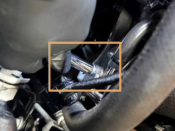
Remove bolt with 12mm socket, 3" extension, and ratchet
-
Remove nut with 12mm socket, 3" extension, and ratchet
-
OE Turbo Inlet Pipe will wiggle freely now
-
-
-
Unfortunately Honda used a single use hose clamps for the turbo inlet pipe. These are difficult to remove
-
Use caution not to damage rubber lines. This is tricky
-
You can use a grinder, Dremel, or perhaps even shears to remove this single use clamp. We prefer Dremel
-
Remove Clamp Shown
-
Partially cut through band of clamp. The idea is to remove enough material that the clamp will break
-
Place flat head screwdriver under cut. If cut enough band will break pretty easily with a bit of pressure
-
-
-
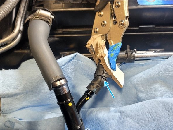
Pop crank breather hose off
-
Use caution as you proceed to minimize coolant leaks
-
Pinch off coolant line in a manner similar to what is shown
-
There are various other tools and ways to accomplish this, like pinch pliers
-
Put towel under coolant line to catch leak
-
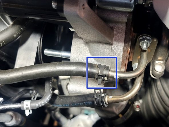
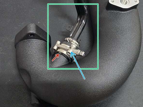
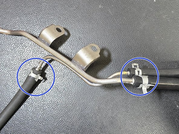
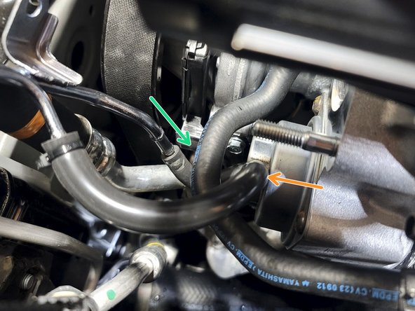
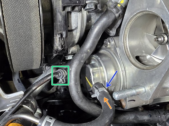
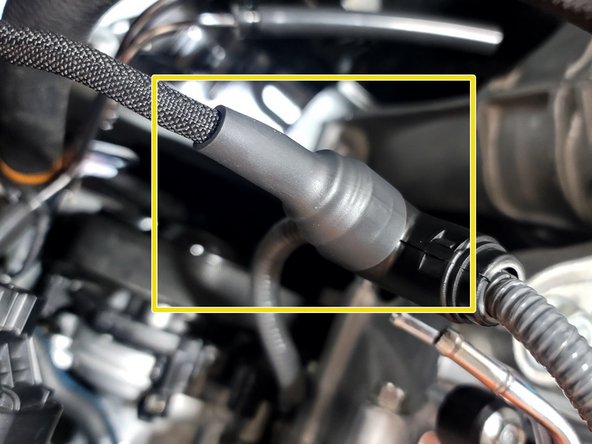
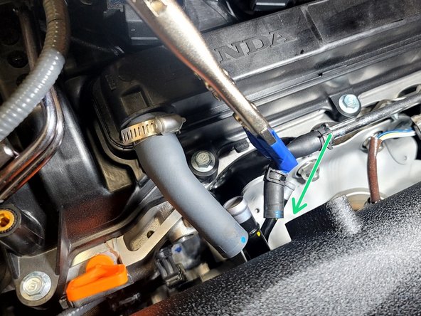
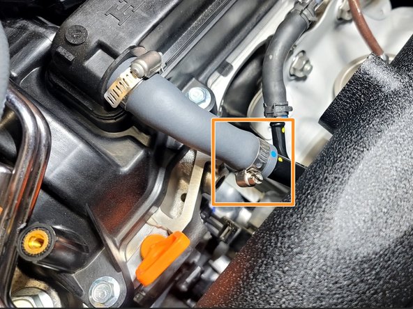
Use pliers to slide clamp out of the way as shown
-
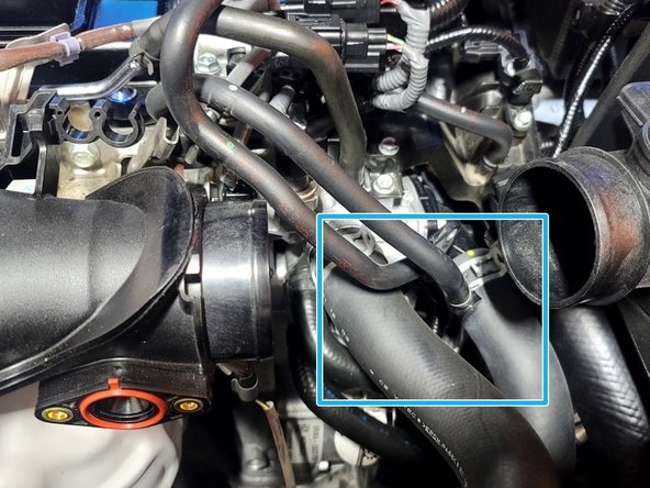
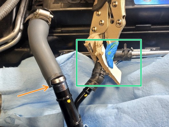
Remove rubber upper coolant feed hose from the TIP hard line
-
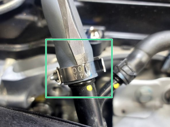
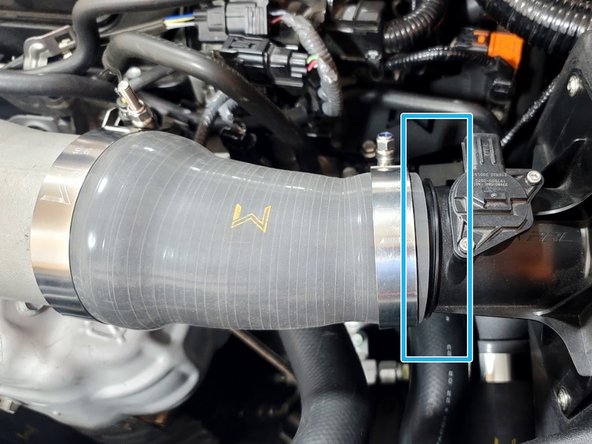
Place towel under the other end of the same line. Slide clamp (blue box) up hose using pliers and remove rubber hose from hard line
-
-
-
Plug coolant line attached to TIP with finger while removing TIP so as to avoid further coolant spills
-
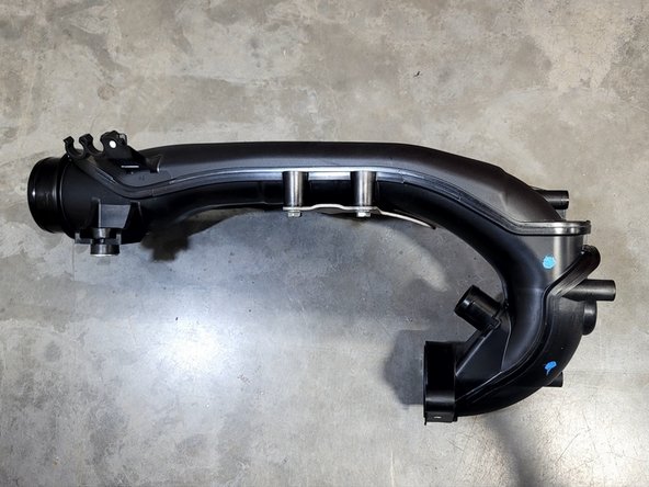
Remove OE TIP from car and set aside
-
-
-
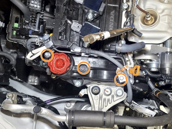
Loosening this bracket will help avoid scratching 27WON TIP during install
-
Use 10mm socket and ratchet to remove three (3) bolts shown
-
Move Vacuum bracket out of the way as shown
-
-
-
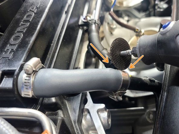
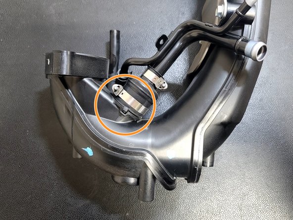
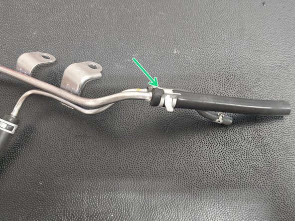
Use caution not to damage the rubber fitting. This is tricky
-
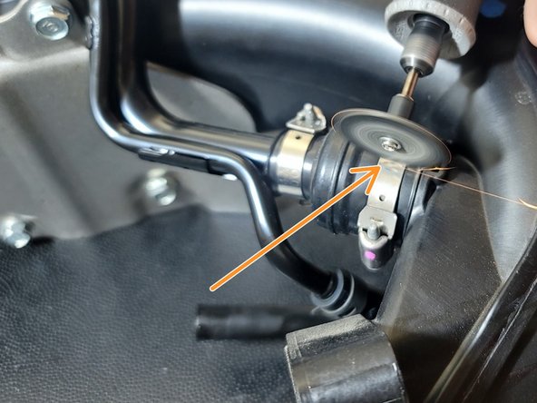
Remove Clamp Shown
-
Partially cut through band of clamp. The idea is to remove enough material that the clamp will break but not so much to cut into the rubber
-
Place flat head screwdriver under cut. If cut enough band will break pretty easily with a bit of pressure
-
A different clamp is shown but the process is the same
-
-
-
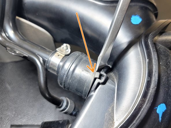
Place screwdriver as shown. Twist and pry while working around the perimeter to break seal and back rubber off the TIP a bit
-
Pull breather hose off OE TIP
-
Orientation of the breather hose assembly is important for ease of reinstallation
-
Place breather hose assembly on 27WON TIP as shown
-
You can cut-off the square nub or leave it on
-
Orient the 32-37mm Hose Clamp as shown and make sure it does not rest on bead roll
-
-
-
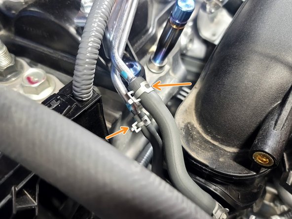
Slide these two (2) clamps up the Bypass Valve and Vacuum line hoses using needle nose pliers
-
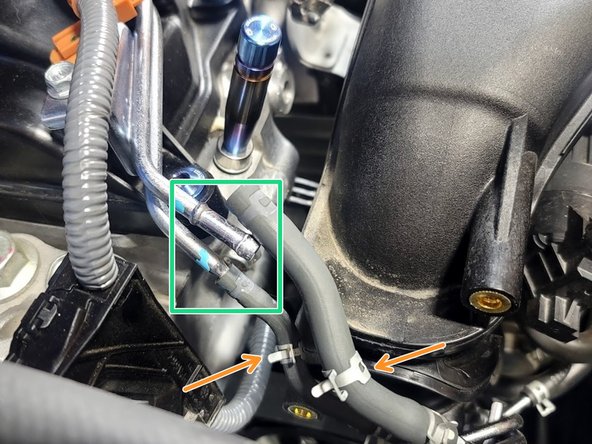
It's helpful to twist rubber hose with hose pliers or by hand before pulling. This will break the seal
-
Pull Vacuum bracket assembly from the car
-
-
-
It's helpful to twist rubber hose with hose pliers or by hand before pulling. This will break the seal
-
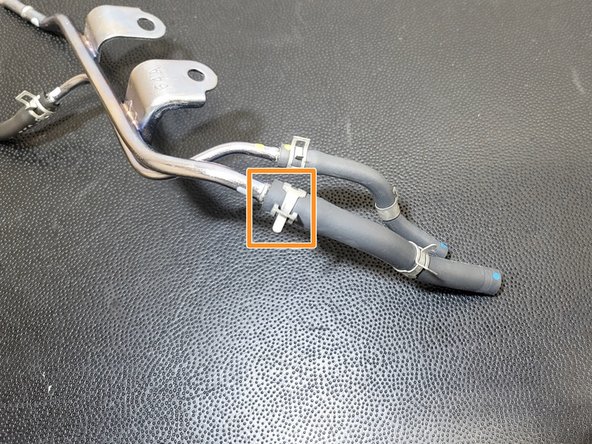
Remove clamp as shown
-
Replace hose with the provided short piece of 5.5mm ID silicone hose
-
Place 13mm spring clamp and secure as shown
-
Spring clamp should slightly depress the silicone hose
-
-
-
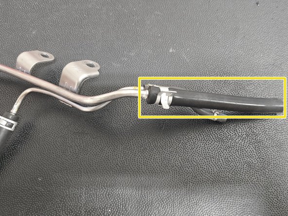
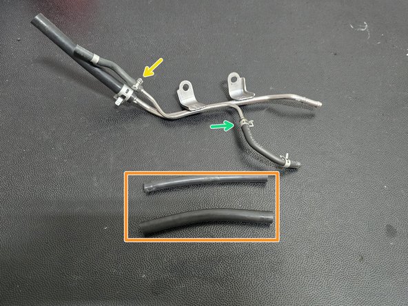
Cut provided 9" long silicone hose in half
-
Remove clamp as shown and replace hose with cut piece of silicone hose
-
Remove clamp as shown and replace hose with cut piece of silicone hose
-
Place 11mm spring clamps as shown
-
Spring clamps should slightly depress the silicone hose
-
-
-
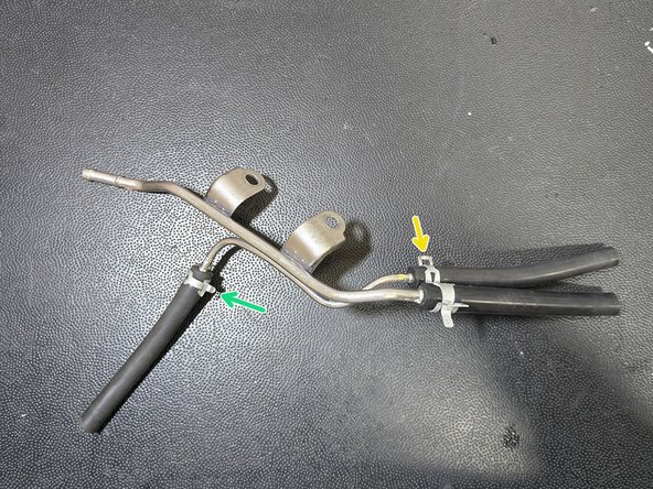
Route new silicone hose over Bypass Valve barb as shown
-
Place OE line over vacuum bracket barb as shown. Using pliers, pull OE clamp up to secure
-
Place 11mm spring clamp on silicone hose as shown
-
Spring clamp should slightly depress the silicone hose
-
-
-
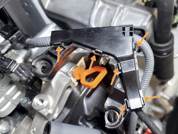
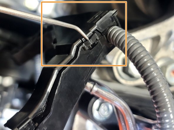
Plastic wire cover breaks easily
-
Use small pick to unclip six (6) clips as shown
-
Open wire cover and remove from car
-
Set plastic cover aside. It will not be reused
-
-
-
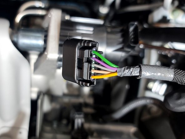
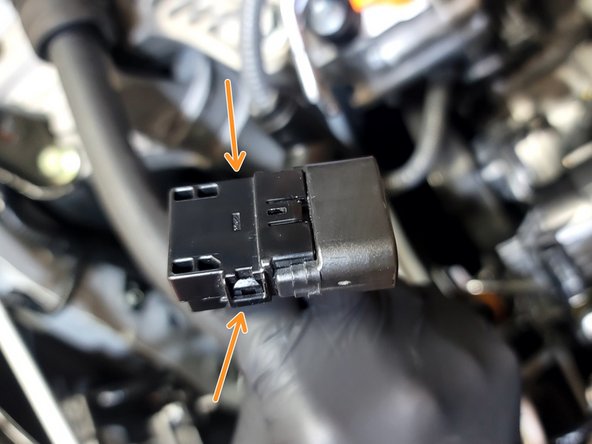
Pop both clips on wastegate actuator plug as shown
-
Remove plastic cover from plug
-
-
-
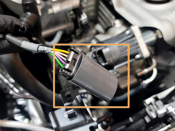
Clip provided Tee in place as shown onto the wiring you uncovered in Step 19
-
Slide provided heat shrink tube over wastegate plug and then up the wire towards the Wiring Loom T-Cover
-
Use heat gun to heat shrink tube. Part of the heat shrink tube should cover the Wiring Loom T-Cover as shown
-
-
-
OPTIONAL: Use electrical tape to seal the other ends of the Tee
-
A 10" cut of tape works well for each end
-
TIP: Electrical tape is stronger when it's not stretched
-
You can use heat gun to smooth out the tape as desired
-
Reinstall wastegate plug cover
-
-
-
Tight spaces. Use caution not to scratch the TIP during install
-
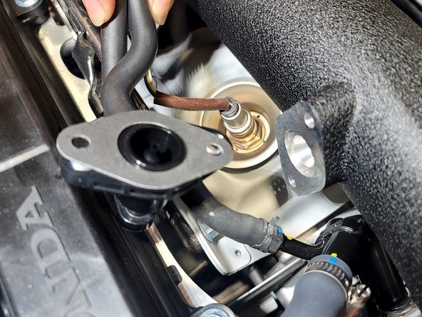
Place provided turbo flange gasket onto turbo as shown
-
Carefully move TIP into position on turbo flange. While doing that use finger to push down rubber hose to clear wastegate actuator
-
Various components will now be attached to the TIP before securing it to the turbocharger
-
-
-
Use pliers and OE clamp to resecure lower rubber coolant feed line to turbocharger
-
Connect upper rubber coolant feed line to hardline
-
Remove Vice Grips
-
Use OE clamp to resecure upper rubber coolant feed line
-
-
-
Use provided hose clamp marked 11-20 to secure OE rubber hose to the hardline
-
-
-
Use provided gasket and attach Evap valve to 27WON TIP using OE T30 hardware
-
-
-
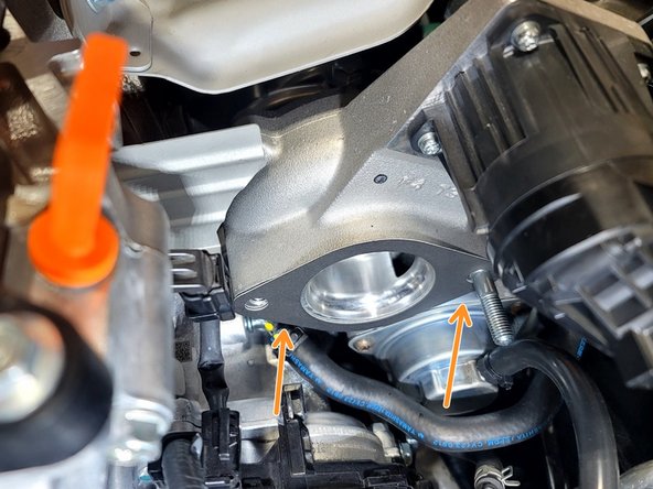
Insert OE bolt into turbocharger as shown using 12mm socket and extension. Tighten to finger tight
-
Wiggle gasket as needed to clear hole
-
Use OE nut to secure TIP to turbocharger stud as shown. Tighten to finger tight
-
Use torque wrench, extension and 12mm socket to secure TIP to turbo at 18 lbf-ft
-
-
-
Use a 10mm socket and ratchet to resecure wiring loom and vacuum bracket from step 13
-
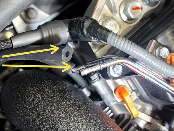
Route Vacuum lines as shown in front of wiring loom
-
Install silicone hoses on Vacuum hard lines
-
Secure silicone hose with 11mm spring clamp as shown
-
Secure silicone hose with 13mm spring clamp as shown
-
-
-
Attach Vacuum line bracket to TIP with provided M5 flange bolts using finger and 8mm socket to set the bolts
-
Use caution not to cross-thread hardware in TIP
-
Wiggle and pull bracket to line up holes to bolts
-
Tighten M5 flange bolts using 8mm socket and ratchet. Torque to 8 lbf-ft
-
Do not overtighten bolts
-
Plug in Wastegate Actuator
-
-
-
Place coolant reservoir back to its original position
-
-
-
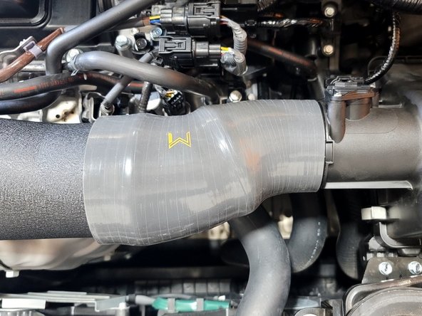
OE Shown. 27WON SRI next step. Other intakes similar
-
Make sure each hose clamp is rotated so that that bolt doesn't poke hood
-
Unclip Lid of OE airbox
-
Install provided 27WON silicone
-
There will be some setting resistance as you close the airbox lid. You can slide the silicone further up the TIP as needed
-
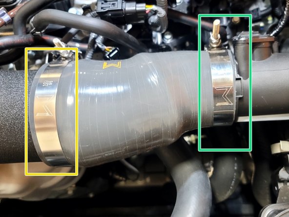
Use provided 95-103mm T-bolt hose clamp on TIP inlet
-
Use provided 73-81mm clamp for OE Intake
-
-
-
27WON SRI shown. PRL intake next step. Other intakes similar
-
Make sure each hose clamp is rotated so that that bolt doesn't poke hood
-
Install provided 27WON silicone
-
Some repositioning of the SRI silicone and/or bracket may be needed when changing from the OE TIP
-
Use provided 95-103mm T-bolt hose clamp on TIP inlet
-
Use provided 70-78mm clamp for 27WON Intake
-
-
-
PRL intake shown
-
Remove PRL silicone to OE tip if still installed
-
Remove three (3) plastic clips securing PRL inlet
-
Remove two (2) bolts to mounting bracket using 10mm socket and ratchet
-
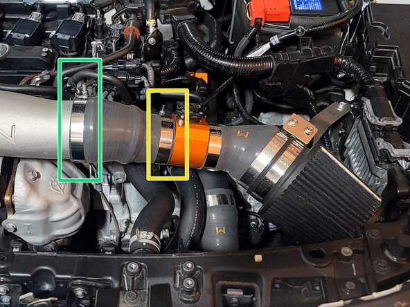
Push provided silicone coupler as far on the 27WON TIP as it will go and rotate it until the MAF end lines up with PRL intake
-
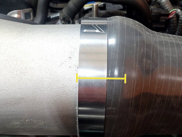
Pull silicone onto MAF until 1.25" remains on the TIP. Secure TIP with provided 95-103mm Hose Clamp as shown
-
The clamp is to the left of the bead roll and the edge of the silicone is right at the edge of the clamp
-
Make sure the bolt on the clamp won't poke the hood liner
-
-
-
PRL intake shown
-
Push PRL intake into silicone. Silicone May appear short as shown
-
Push intake and silicone together and secure with provided 73-81mm Hose Clamp
-
A small gap of 1-2mm is ok here
-
Reconnect intake bracket with two 10mm bolts using socket and ratchet
-
Reconnect Inlet with plastic clips
-
-
-
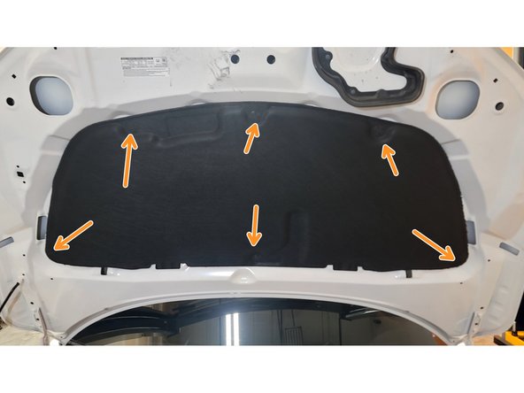
Clearance from 27WON TIP to hood insulation is minimal. Repositioning the hood insulation will add space. This step is optional
-
There is plenty of clearance between 27WON TIP and the metal hood behind insulation
-
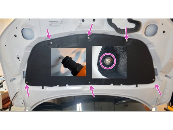
This step requires a Riv-Nut installation tool with M5 adapter
-
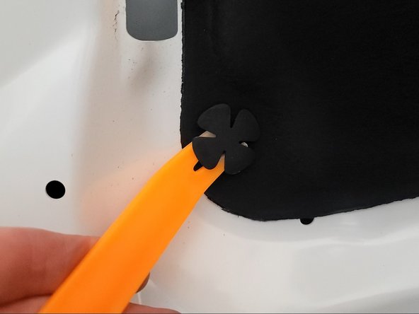
Remove six (6) plastic clips that hold hood insulation in place using clip removal tool
-
Install six (6) M5 Riv-Nuts
-
Allow insulation to hang as low as possible
-
Install provided M5 cap screws using 3mm hex wrench
-
-
-
To get the best performance from your 27Won Turbo Inlet Pipe, we recommend a custom tune
-
A custom tune for your specific vehicle with your specific modifications will provide the best performance for your Civic/Integra and the location you live in
-
Lots of hoses were disconnected during this install. Any hoses with clamps removed during install should be properly secured. CEL Code P0088 or others is a clue a connection may be leaking
-
CEL Code P2565 could indicate a bad connection at the wastegate. Pull plug and clean connectors if this happens
-
-
-
This completes the installation of your 27WON Performance Turbo Inlet Pipe
-
We hope you were impressed with your 27WON experience and love your new TIP for years to come. Email us at sales@27won.com or call us at 571-271-0271 with any questions or concerns
-
Please leave a review here: https://store.27won.com/2022-1.5t-civic-...
-
Share your experience using #27WON on Instagram and Facebook
-