Introduction
In this installation guide we have provided step by step instructions to setup, remove the OEM intake system, and install the 27WON Performance Cold Air Intake.
Advisory:
- Working under the vehicle requires a safe and sturdy location for the vehicle to sit on jackstands.
- The engine bay will be hot after recent vehicle operation. Allow the vehicle to cool or use a fan to cool the engine bay before working on the vehicle.
Tools
Parts
- L15 CAI Airbox
- Airbox Lid
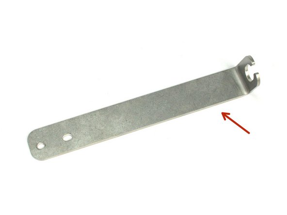
- L15 CAI Long Bracket
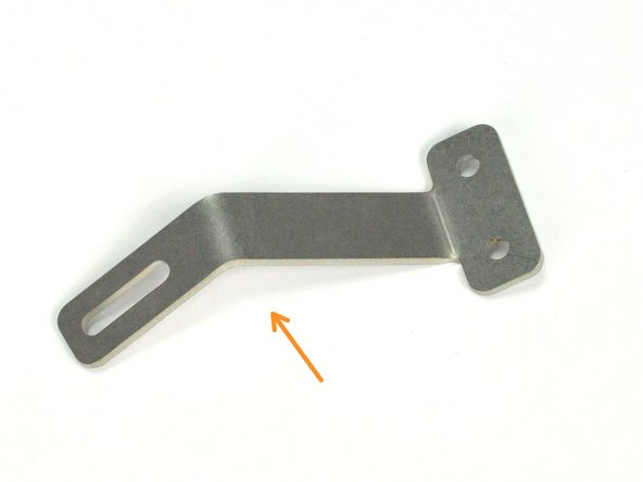
- L15 CAI Short Bracket
- L15 CAI MAF Housing
- Silicone Coupler - MAF to TIP
- Silicone Coupler - Airbox to MAF
- Air Filter
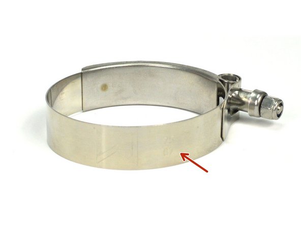
- T-Bolt Clamp - 67-75mm × 3
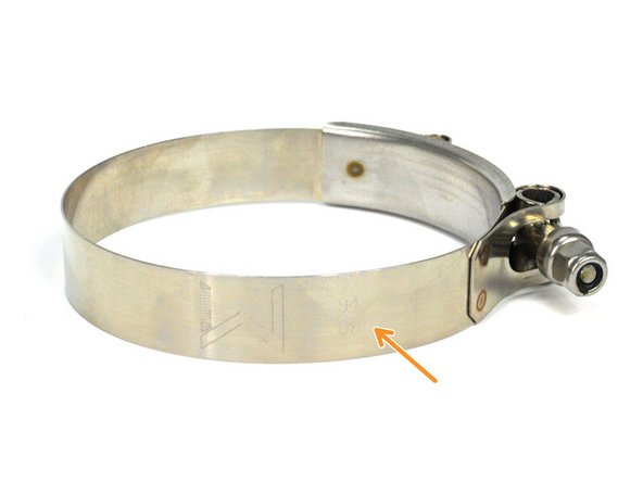
- T-Bolt Clamp - 86-94mm
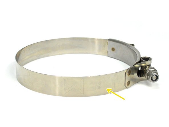
- T-Bolt Clamp - 108-116mm
- Standoff Rubber Isolator - M6x1.0
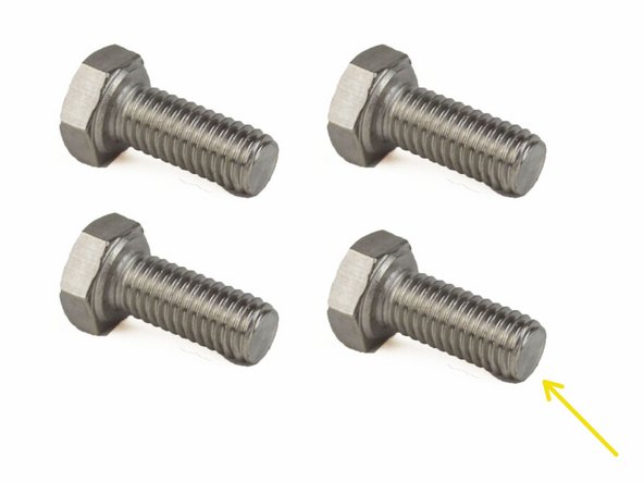
- SS Hex Head Screw - M5x0.8x12mm × 4
- SS Flange Button Head Screw - M5x0.8x16mm × 4
- SS Flange Nut - M6x1.0
- Rubber Dampener M6x1.0
- SS Hex Head Bolt- M6x1.0x8mm
-
-
First and foremost; THANK YOU for becoming a part of the 27WON Family. We hope to REDEFINE your experience of the aftermarket with the highest level Parts, Customer Service, Packaging, & Support
-
Aftermarket transmission coolers may not fit with our intake
-
-
-
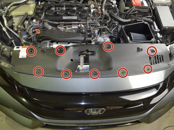
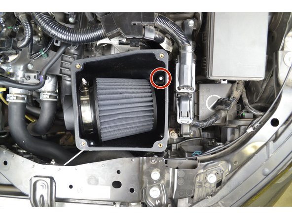
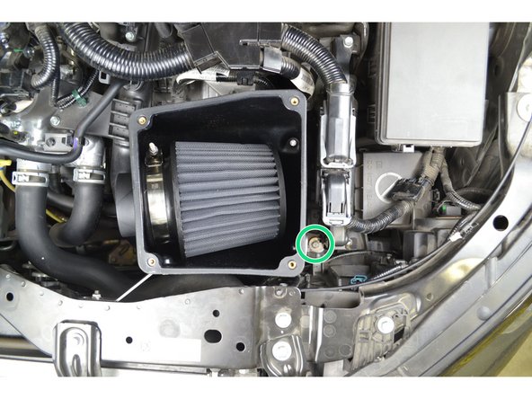
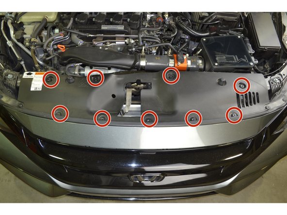
Locate the engine under tray to gain access to the OE lower airbox
-
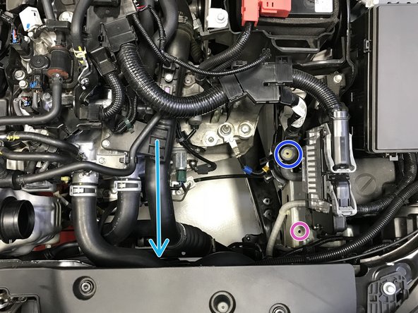
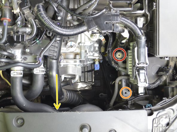
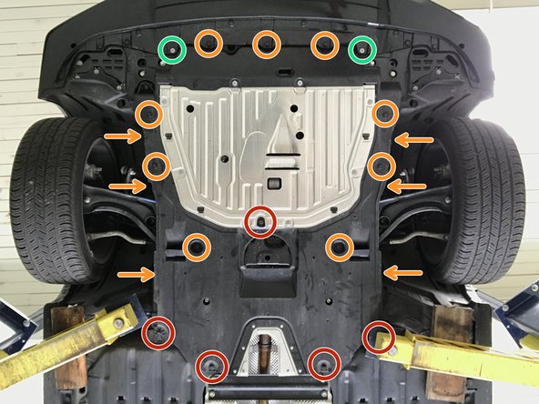
Use 5mm Allen Key to remove the two (2) bolts shown in green circles
-
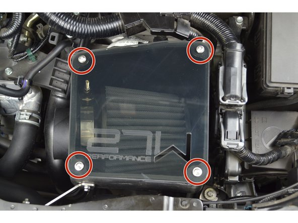
Use 10mm socket & ratchet to remove the seven (7) bolts shown in red circles
-
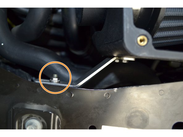
Use a flathead screwdriver to remove the seventeen (17) plastic push-clips. Orange arrows identify the push-clips in described in the next step (3)
-
-
-
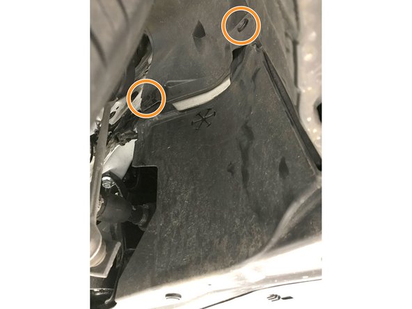
Use large flat head screw driver to remove push-clips on each side of skidtray
-
-
-
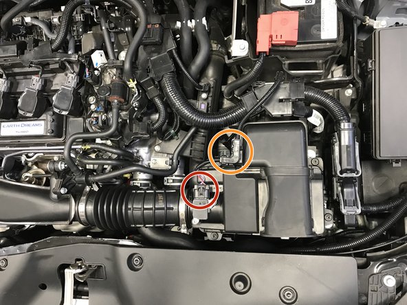
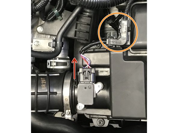
Disconnect the wiring harness from the MAF Sensor
-
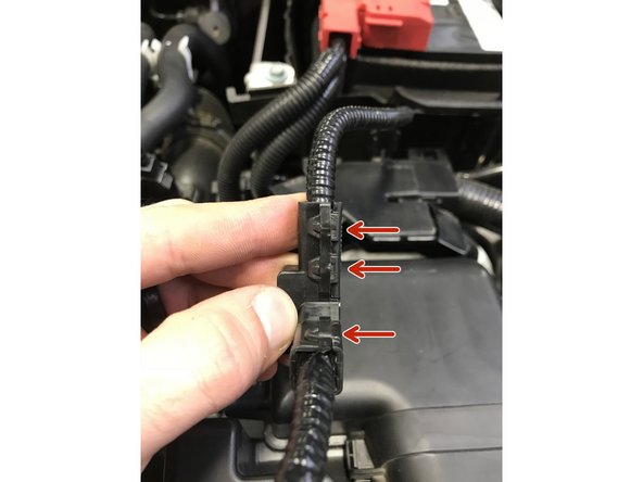
Remove the wire cover from the airbox
-
Use needle noise pliers to pinch the clips then pull the cover off the airbox
-
-
-
The MAF wire cover consist of two halves that are held together by push lock clips. These will need to be unlocked to remove the cover
-
Step 6 will show how to pull apart MAF wire cover
-
-
-
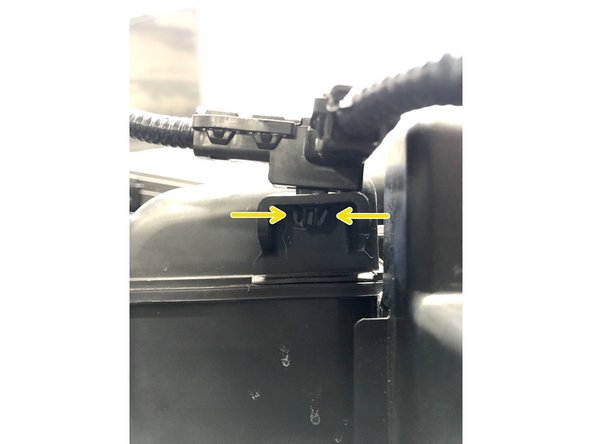
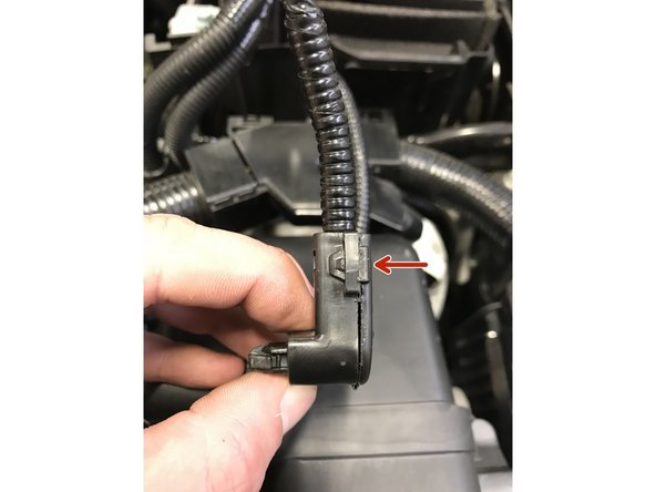
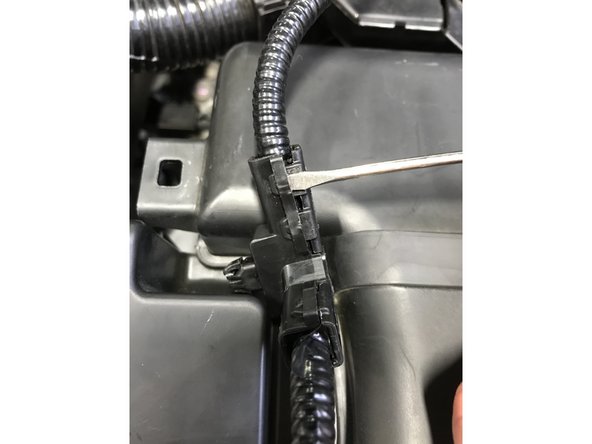
Using small flathead screwdriver, gently pry between the square loop and the prong, then pry the prong out of the loop
-
It takes very little force to insert the flathead screwdriver and pry loose, try not to break the square loop
-
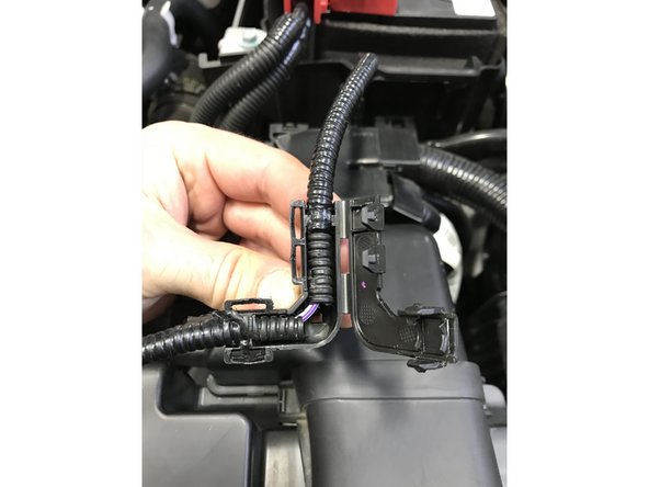
With all four prongs unlocked the cover should open as shown
-
Pull the wire out of the cover and wrap the exposed section in electrical tape
-
-
-
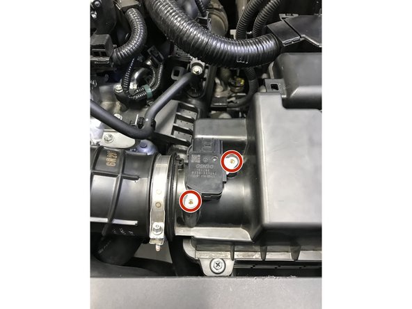
Use a small Phillips screwdriver to remove the two screws
-
Remove the MAF sensor from the airbox and reinstall the OE screws into the airbox, they are not used in the 27WON CAI
-
Base Model MAF Sensor shown, SI MAF Sensor removal is same
-
-
-
Use a 5.5mm socket to loosen the hose clamp
-
A small phillips screwdriver can be used, but is not recommend because the hose clamp head strips easily
-
-
-
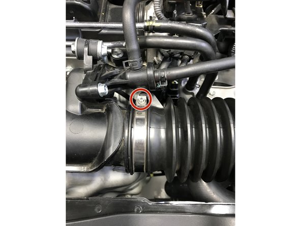
Use a 10mm socket and long extension to unthread the two silver mounting bolts
-
You can leave the bolts loose in position during airbox removal
-
-
-
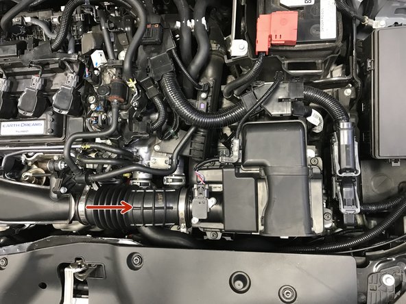
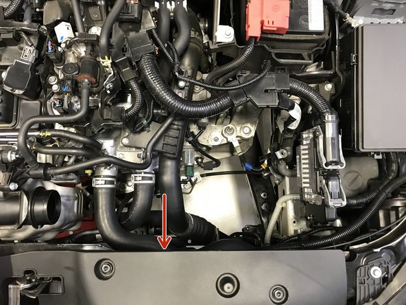
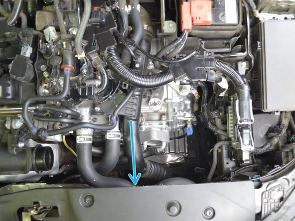
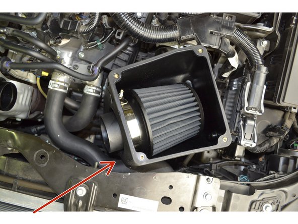
Pull the hose off the turbo inlet pipe in the direction of the arrow
-
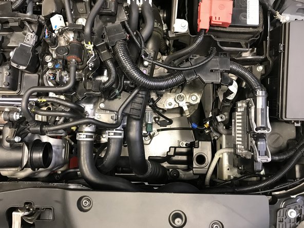
With the hose loose, remove the entire airbox from the engine bay
-
The result will look as shown in the second image
-
-
-
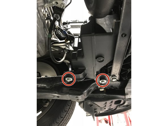
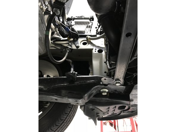
From under the vehicle locate the two bolts, use a 10mm socket & ratchet to remove the two bolts
-
Remove the lower airbox assembly from the vehicle
-
The result will look as shown in the second image
-
-
-
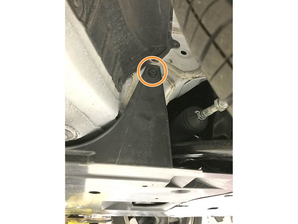
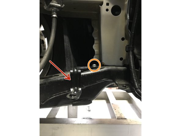
From under the vehicle, locate lower airbox assembly mounting bracket
-
Use a 10mm socket & ratchet to remove the bolt
-
Remove the bracket from the vehicle
-
-
-
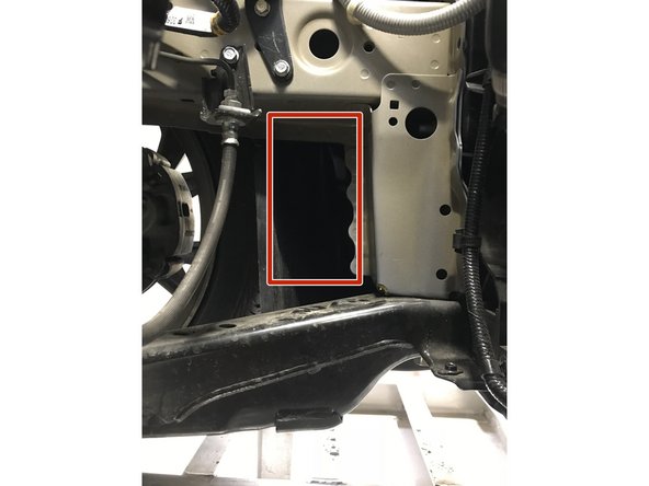
The red square shows where the lower inlet of the airbox will sit in the engine bay and fender well
-
-
-
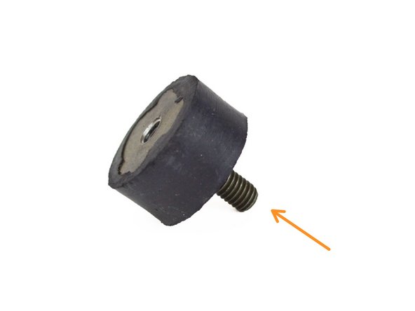
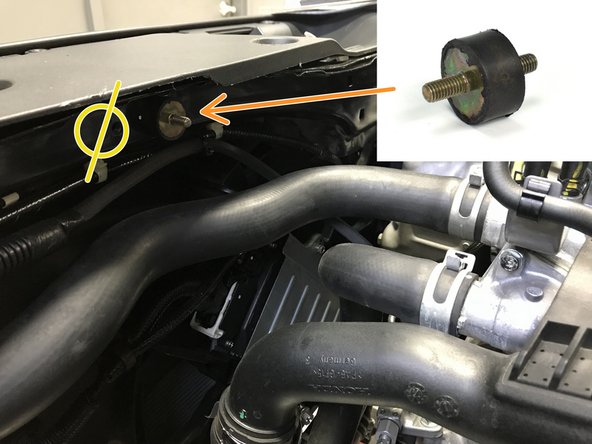
Locate the provided rubber isolator standoff for step 15
-
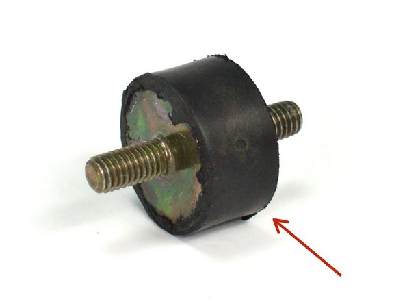
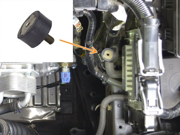
Locate the provided rubber dampener for step 16
-
-
-
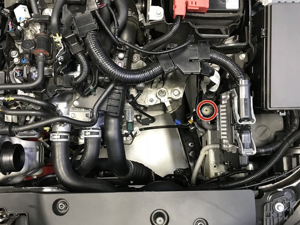
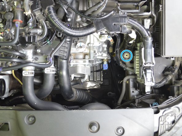
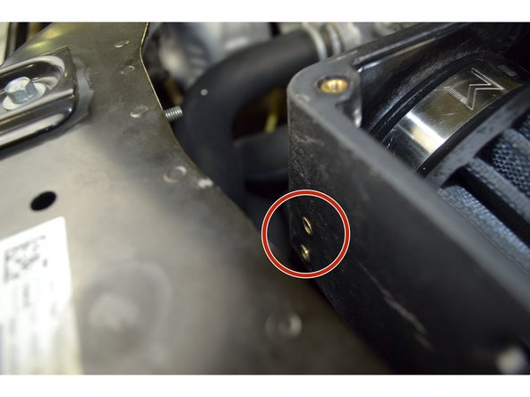
Locate threaded hole in the core support for manual transmissions
-
Locate threaded hole in the core support for Automatic transmissions
-
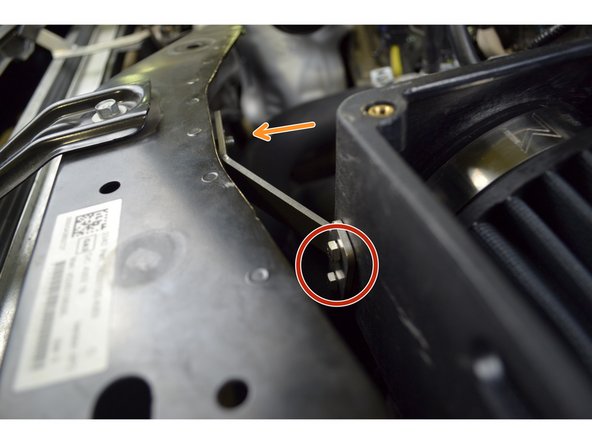
Install the rubber isolator standoff in the threaded hole closest to the turbocharger. Tighten hand tight using your fingers
-
There are two threaded holes located in the core support, use the hole closest to the turbocharger. Don't use the hole marked in yellow
-
-
-
Locate threaded hole in the bracket for manual transmissions
-
Locate threaded hole in the bracket for Automatic transmissions
-
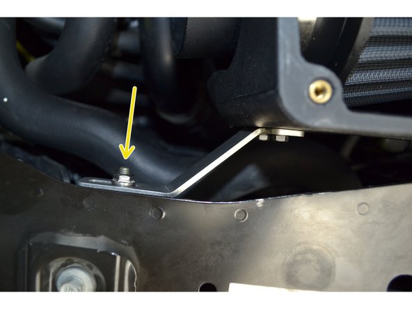
Install the rubber dampener in the threaded hole found in the bracket, tight hand tight with fingers
-
The bracket is mounted to the chassis rail next to the ECU
-
-
-
Carefully pry the 9 plastic clips open with a flat head screw driver
-
Clips are fragile and can easily break if to much force is applied
-
-
-
Locate the OE Airbox Assembly
-
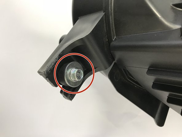
Identify one of the OE rubber mounts and remove the OE bolt (the bolt should be loose in the mount)
-
Keep this bolt, it will be used later
-
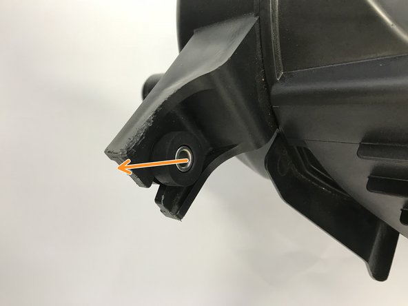
Press the metal collar out of the rubber mount with your hands.
-
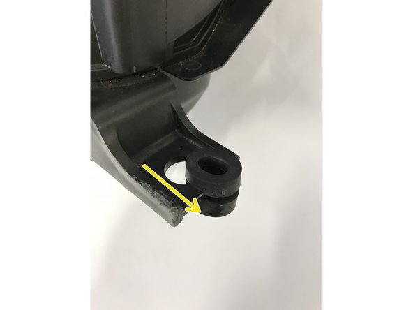
Pinch the rubber mount together then remove the rubber mount from the OE airbox assembly
-
-
-
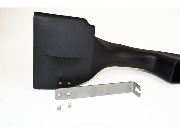
Locate the Long Bracket
-
Locate the Short Bracket
-
Locate QTY=4 M5x0.8x12mm Hex Head Bolts
-
-
-
Install the OE rubber mount and steel collar as shown
-
-
-
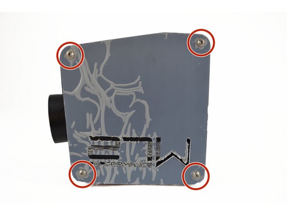
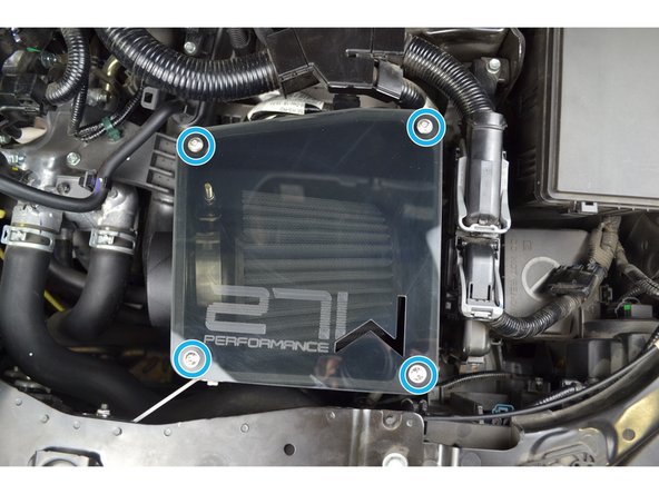
Use a 3mm Allen Key to remove the four flanged button head bolts holding the lid on
-
Remove the protective cover on the lid and set the lid aside on a non-abrasive surface
-
Unwanted scratches could occur if lid is not handled with care
-
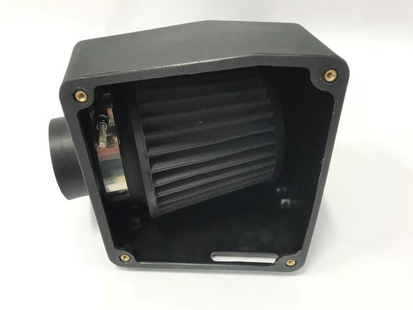
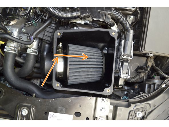
With the lid removed you now have access to the air filter and the inner airbox mounting location
-
-
-
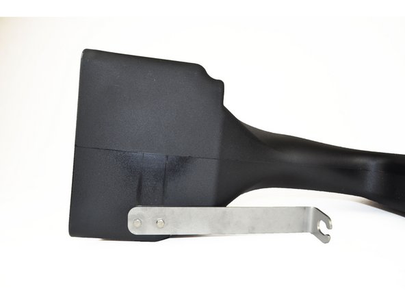
Using a 8mm socket and ratchet, install the bracket as shown
-
Torque bolts to 24-48 in-lbs
-
-
-
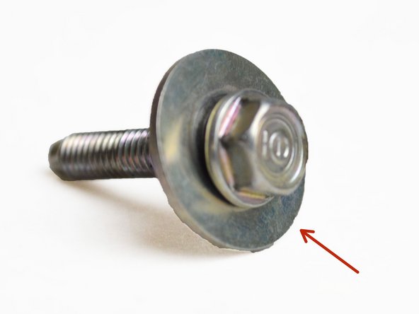
Locate the OE airbox mounting bolt
-
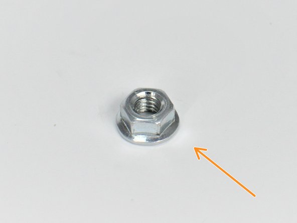
Locate the provided QTY=1 M6x1.0 Flange Nut
-
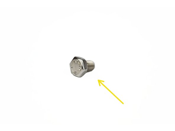
Locate the provided QTY=1 M6x1.0 Hex Head Bolt
-
-
-
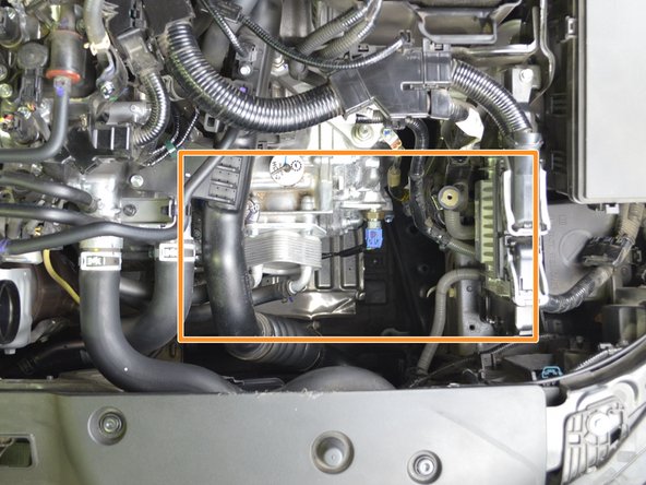
This Clearance warning applies to vehicles with automatic transmissions. Skip step if vehicle has a manual transmission.
-
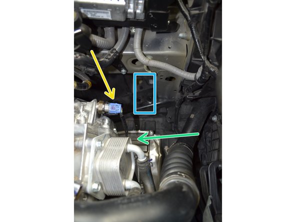
Inside the orange box there are multiple tight clearances due to the CVT.
-
Be careful not to run into this sensor. The airbox will clear the sensor but carelessness when inserting the box could damage the sensor
-
The bottom of the airbox fits right into this square opening
-
In some cars, airbox may touch this sensor. It is ok. Give us a call if this concerns you
-
Be careful not to run into the transmission cooler. The airbox will clear the cooler but carelessness when inserting the airbox could damage the airbox
-
Aftermarket transmission coolers may not fit with our intake
-
-
-
Before positioning the 27WON airbox into the engine bay, please identify the correct mounting locations
-
Manual transmission inner airbox mounting point
-
Manual transmission long bracket mounting point
-
Manual transmission short bracket mounting point
-
Automatic transmission inner airbox mounting point
-
Automatic transmission long bracket mounting point
-
Automatic transmission short bracket mounting point
-
-
-
Lower the 27WON airbox into the engine in the orientation shown.
-
Swivel the airbox into position
-
-
-
Now that the airbox is in position. Attach the provided short bracket to the airbox with (2) M5x0.8X12mm hex head bolts and a 8mm wrench
-
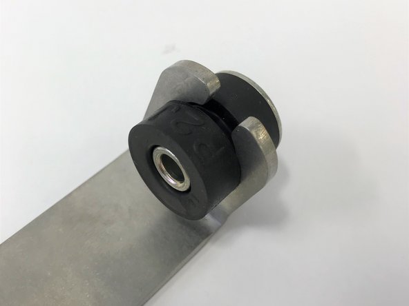
Aline the slotted end of the short bracket onto the rubber isolator
-
Thread the provided M6x1.0 flange nut onto the rubber isolator. The nut should be loose enough to allow the airbox to still slide within the slotted hole
-
-
-
Aline the inner hole with the hole in the rubber dampener and insert the provided hex head M6x8mm bolt. Tighten using a 10mm socket with an extension and a ratchet
-
Tighten the bolt to 12-24 in-lbs
-
Do not over tighten the bolt. This could damage the airbox.
-
-
-
Aline on the Long bracket with the threaded hole in the chassis
-
Insert the OE bolt into the long bracket
-
Tighten with a 10mm socket with extension and ratchet, Torque the OE bolt in the long bracket to 36-48 in-lbs
-
-
-
Tighten the M6x1.0 flange nut on the rubber isolator using a 10mm socket and ratchet to 24-36 in-lbs
-
-
-
Place the airbox lid onto the airbox
-
Install the four M5x0.5x16mm flanged button head bolts, Tighten the bolts to 12 in-lbs
-
The lid can crack if significantly over-tightened.
-
If the holes in the lid do not want to align exactly with the threaded inserts, you can lightly twist/push the airbox. The mounting process can distort the shape of the bow slightly. This is nothing to worry about
-
-
-
The MAF housing comes assembled with the necessary MAF sensor installation hardware
-
The MAF housing has a small cutout at the top for the wiring harness. This cutout will face the rear of the vehicle once installed
-
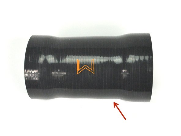
Silicone coupler between the MAF housing and the OE turbo inlet pipe
-
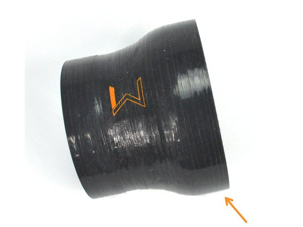
Silicone coupler between the MAF housing and the airbox
-
On both silicone couplers there is a "W" logo. The bottom of the "W" will face the front of the vehicle once installed
-
-
-
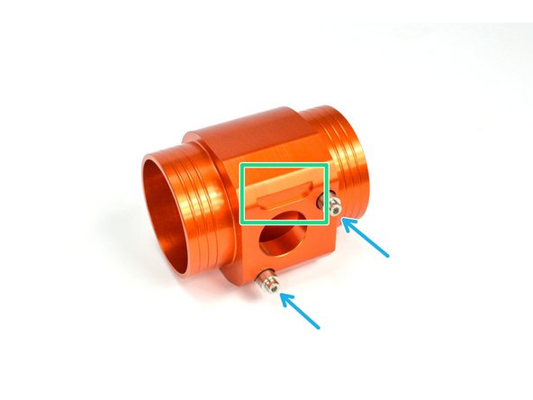
Use a 3mm Allen Key to remove the socket cap bolts from the MAF housing
-
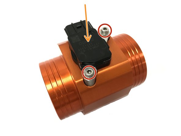
Install the MAF sensor into the housing
-
If you are having issues, push the sensor into the housing while turning the sensor, this should help
-
Be careful to not pinch and damage the o-ring on the sensor
-
Align the sensor with the stainless steel standoff and install the socket cap bolts
-
Torque the socket cap bolts to 24-48 in-lbs
-
-
-
Locate the provided QTY=1 67-75mm clamps.
-
Locate the provided QTY=1 86-94mm clamp
-
The 108-116mm clamp is already installed on the air filter
-
-
-
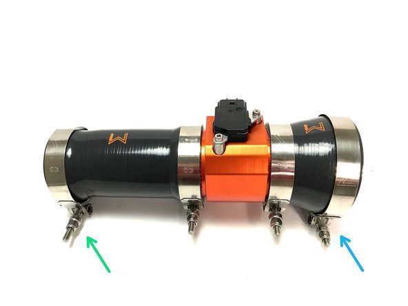
Verify that your MAF & Silicone Assembly has came as shown
-
Install the 67-75mm clamp loose as shown
-
Install the 86-94mm clamp loose as shown
-
A small gap between the end of the silicone and the MAF housing is normal. This is required for proper connection of the internal step in the silicone
-
-
-
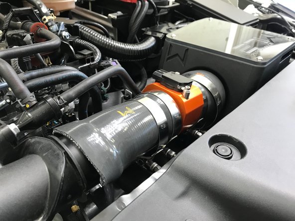
Angle the MAF & Silicone assembly into the engine bay and onto the airbox
-
Verify the silicone coupler connecting to the airbox is over the circumference of the airbox outlet
-
-
-
Pivot the MAF & Silicone assembly down and onto the turbo inlet pipe
-
The silicone coupler is flexible enough to bend and distort as needed to fit over the turbo inlet pipe
-
Adjust the silicone coupler to fit around the entrance of the turbo inlet pipe
-
-
-
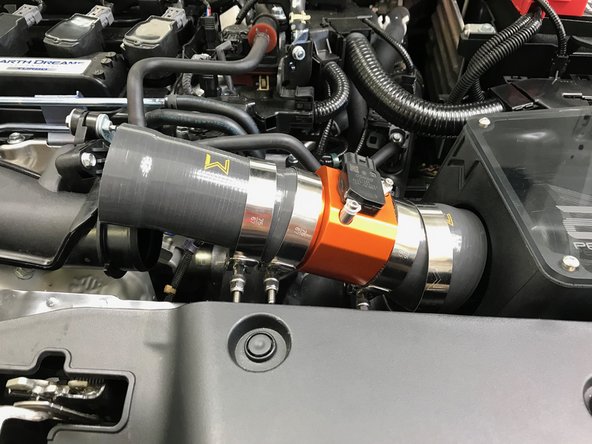
If needed, rotate the MAF & Silicone assembly so the MAF sensor and "W" are facing upward as shown
-
Use a 10mm wrench or socket and wrench to tighten the 86-94mm clamp on the airbox
-
Use a 10mm wrench or socket and wrench to tighten the 67-75mm clamp on the turbo inlet pipe
-
Tighten the clamps until snug (the silicone will start to bulge at the edge of the clamp slightly)
-
-
-
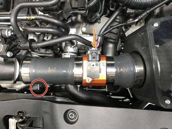
Connect the wiring harness to the MAF sensor as shown
-
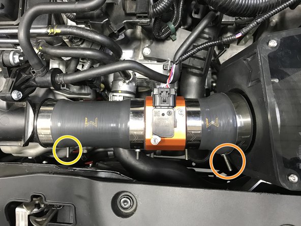
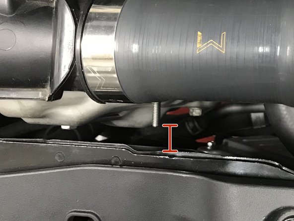
Check clearance of the clamp at the turbo inlet pipe, verify there is approximately 3/4" clearance from the end of the T-bolt rod to the core support. Rotate clamp to adjust if necessary
-
-
-
Reinstall radiator fan guard by inserting the 9 plastic clips and pressing down on them with your thumb
-
-
-
Re-install the 10mm bolts with a 10mm socket & torque wrench. Torque to 8-12 ft-lbs
-
Re-install the 5mm socket flange bolts with the 5mm Allen key & torque wrench. Torque to 6-8 ft-lbs
-
Re-install the push clips at the bottom of the undertray and the sides (shown in Step 2)
-
-
-
Re-install the push clips at the side of the undertray
-
-
-
This completes the installation of your 27WON Performance Cold Air Intake System.
-
We hope you were impressed with your 27WON experience and love your new Cold Air Intake for years to come. Email us at sales@27won.com or call us at 571-271-0271 with any questions or concerns
-
We recommend going to the next step to learn how to service the air filter or check our video on cleaning the air filter at https://youtu.be/nE7diTeI4Gw
-
Please Leave a review here: https://store.27won.com/10th-gen-civic-c...
-
Share your experience using #27WON on Instagram and Facebook
-
-
-
The next step explains how to remove and reinstall your air filter for cleaning and service.
-
When re-installing your air filter be careful not to compress the velocity stack on the air box to a point of deformation. Doing so can cause the air box to crack and the air filter to fall off
-
-
-
Here we show how to remove the air filter for standard maintenence
-
Use a 3mm Allen Key to remove the four bolts, then remove the airbox lid
-
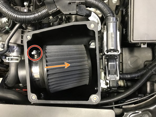
Use a 10mm socket and wrench to loosen the clamp
-
Pull the air filter off the airbox velocity stack then pull the filter straight up and out of the airbox
-
The air filter is a tight squeeze to remove, do not worry if the airbox or air filter flex or distorts slightly
-
Reinstall the air filter in the reverse order.
-
Hold the air filter tight against the airbox velocity stack and tighten the clamp snug. Verify the air filter cannot be pulled loose with a gentle tug
-
Verify that the T-bolt rod is not protruded past the top of the airbox, this would damage the airbox lid
-