Introduction
In this installation guide we have provided step by step instructions to remove the OEM turbo inlet pipe and install the 27WON Performance Turbo Inlet Pipe.
Advisory:
- Some non-permanent modifications to metal piping and the wiring loom must be made to install the 27WON Turbo Inlet Pipe.
- The exhaust piping, turbocharger, and cooling system will be hot after recent vehicle operation. Allow the vehicle to cool or use a fan to cool the exhaust components before working on the vehicle.
Tools
- Silicone Lubricant Spray
- Shop Towels/Rags
- Flat Head Screwdriver - Large
- Flathead Screwdriver - Small
- Phillips Screwdriver - #2
- Tongue and Groove Adjustable Pliers
- Pliers - Small
- Socket 8mm
- Socket, 10mm
- Socket 12mm
- Socket 13mm
- Socket 14mm
- Socket 17mm
- Ratchet Wrench Extension - Short
- Ratchet Wrench Extension - Long
- Ratchet Wrench
- Wrench 9mm
- Wrench, 10mm
- Wrench, 12mm
- Wrench, 14mm
- Wrench, 17mm
- Wrench, 19mm
- Allen Wrench 3mm
- Allen Wrench 5mm
- Torque Wrench
- Magnet on a Stick
- Heat Gun
Parts
- Assembled Turbo Inlet Pipe
- T-Bolt Clamp - 86-94mm
- Worm Gear Clamp 14-27mm × 2
- Stainless Steel Formed Bracket
- M8x1.25x80mm Flange Bolt - Stainless Steel × 2
- M8x1.25x35mm Stud - Stainless Steel × 2
- M8x1.25 Flange Nut - Stainless Steel × 2
- Valve Cover Breather Hose
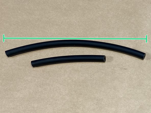
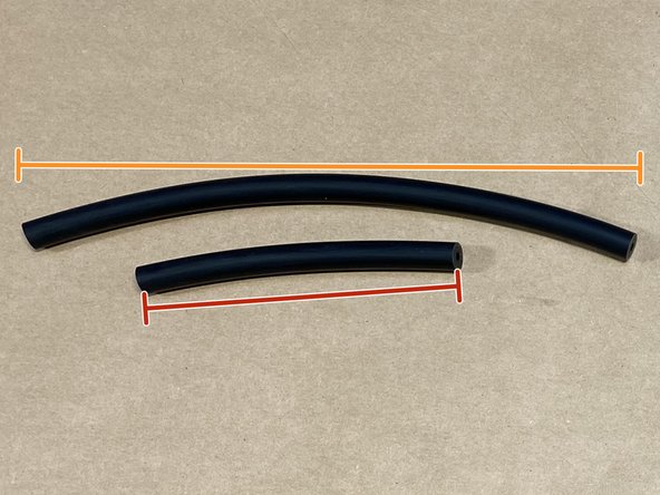
- 4mm Black Silicone Hose - 5in Length
- 4mm Black Silicone Hose - 10in Length
- Turbo Inlet Pipe Gasket
- Vacuum Shrink Wrap Tubing - 2in Length
- Wiring Loom T-Cover
- O-Ring - Brown
- Loop Clamp - 5/16in
-
-
First and foremost; THANK YOU for becoming a part of the 27WON Family. We hope to REDEFINE your experience of the aftermarket with the highest level Parts, Customer Service, Packaging, & Support.
-
Every turbo inlet pipe has been cast in aluminum and and hand finished to guarantee quality and superior fitment. Due to the artisan casting, every turbo inlet pipe is unique and serialized for authenticity.
-
The turbo inlet pipe used for these instructions was a pre-production prototype that was not powder coated - installation is identical, but your turbo inlet pipe is powdercoated
-
-
-
Due to the design and pursuit for peak performance, the 27WON Turbo Inlet Pipe does not fit exactly like OEM. To provide you with the easiest & best possible fitment, we have developed silicone couplers to fit the common intake systems currently available
-
For Intake Removal:
-
Step 3 for 27WON Intake Systems
-
Step 3 for PRL & Generic 2.5" Pipe Intake Systems
-
-
-
The OEM Intake system is not compatible with the 27WON turbo inlet pipe
-
Disconnect the wiring harness from the MAF Sensor
-
Use a 10mm wrench or socket to loosen the Qty(2) T-bolt clamps circled
-
Pull the silicone coupler loose from the OEM turbo inlet pipe as shown
-
Pull the complete silicone and MAF housing assembly from the 27WON cold air box
-
-
-
PRL Intakes
-
Loosen the clamp at the OEM turbo inlet pipe - typically a flathead screwdriver can be used
-
Loosen the clamp at the MAF housing - typically a flathead screwdriver can be used
-
Remove the silicone coupler from the engine bay
-
Generic Intakes with 2.50in Piping
-
Loosen both clamps at the OEM turbo inlet pipe - typically a flathead screwdriver can be used
-
Loosen the clamp that connects the pipe section to the rest of the intake - typically a flathead screwdriver can be used
-
Disconnect the MAF sensor wire then remove the pipe section from the engine bay
-
-
-
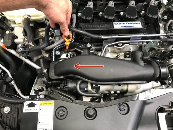
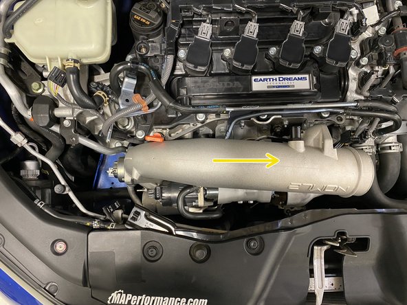
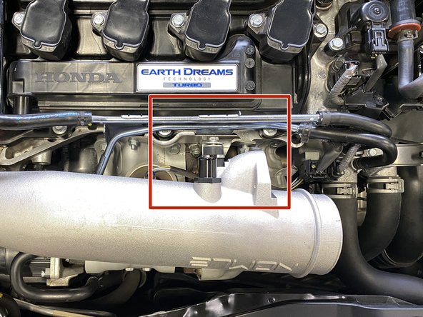
Going forward we will reference the black plastic pipe connected to the turbo as the "Turbo Inlet Pipe (TIP)"
-
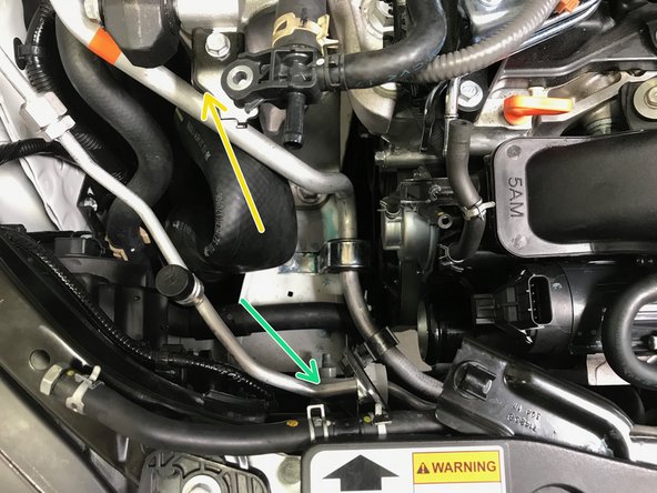
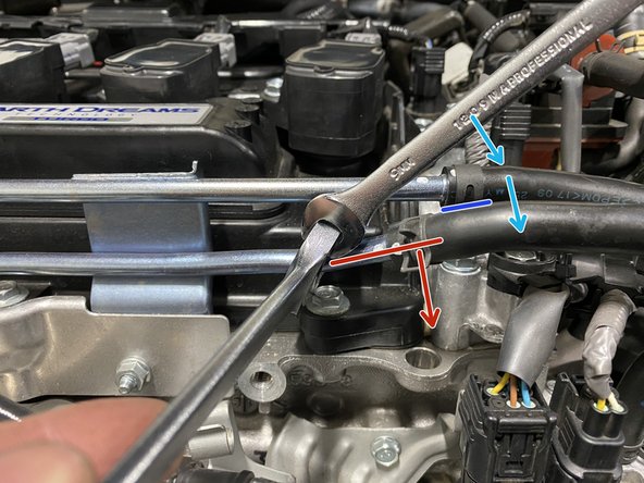
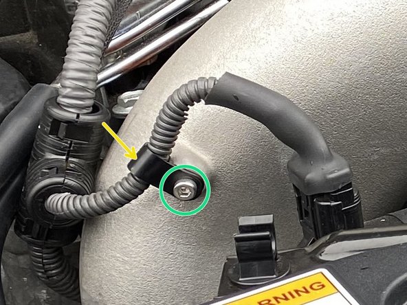
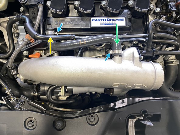
The following components are identified for clarity in the following steps
-
EVAP Bleed Air Valve
-
Valve Cover Breather Hose
-
TIP Mounting Points
-
Waste Gate Actuator (WGA) Wiring Connection
-
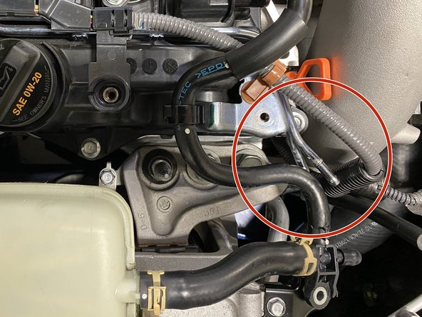
By-Pass Valve (BPV) Hoses
-
-
-
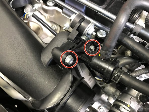
Use a 10mm socket & ratchet to remove the two (2) 10mm bolts
-
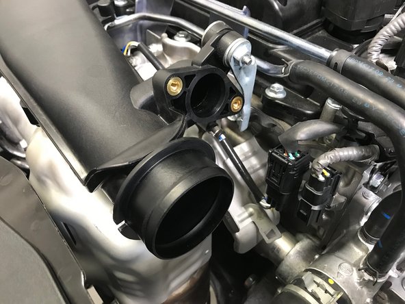
Pull the EVAP bleed air valve out of the TIP and set to the side
-
-
-
Use pliers to loosen the spring clamps. Slide the clamps towards the center of the hose
-
Pull the hose off the valve cover first
-
Pull the hose off the TIP second
-
-
-
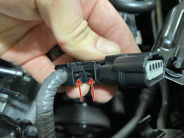
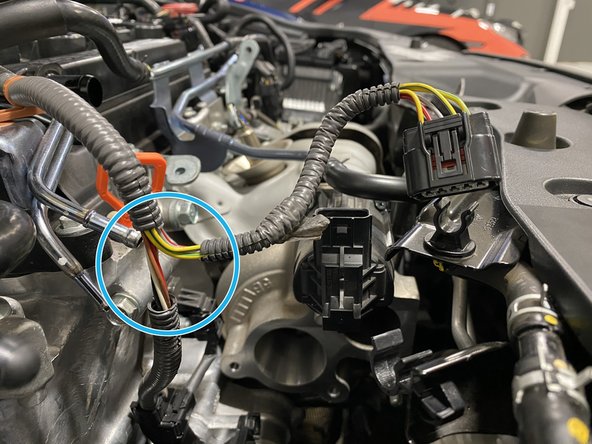
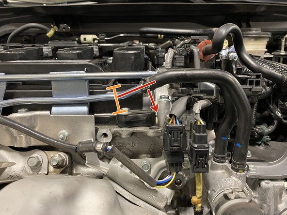
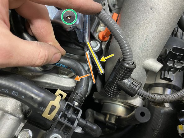
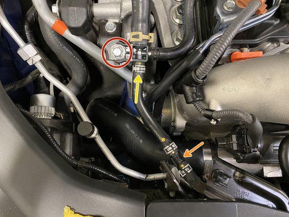
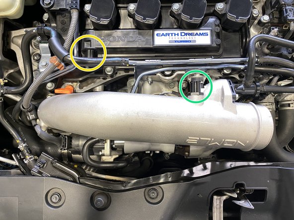
Disconnect the wiring from the Waste Gate Actuator (WGA)
-
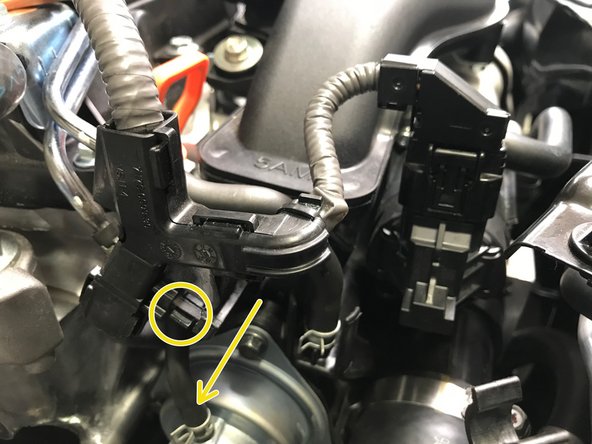
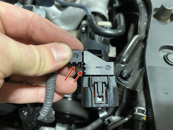
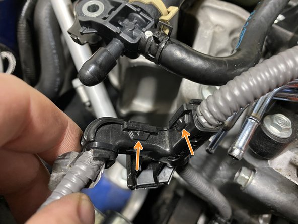
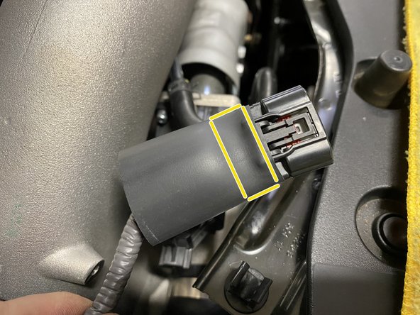
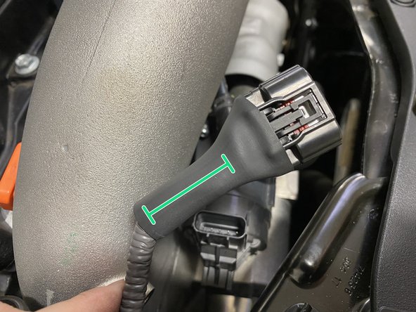
Locate the wiring loom
-
Press down on the small tab and pull the wiring loom from the bracket in the direction of the yellow arrow
-
Move the wiring harness towards the rear of the car out of the way
-
-
-
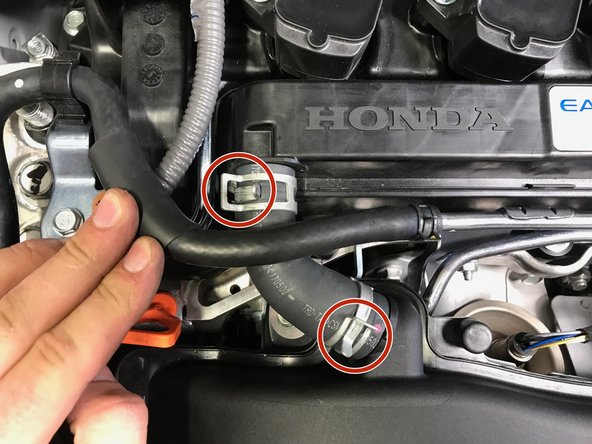
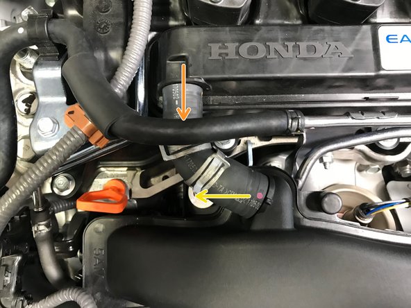
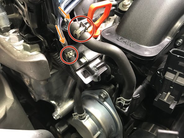
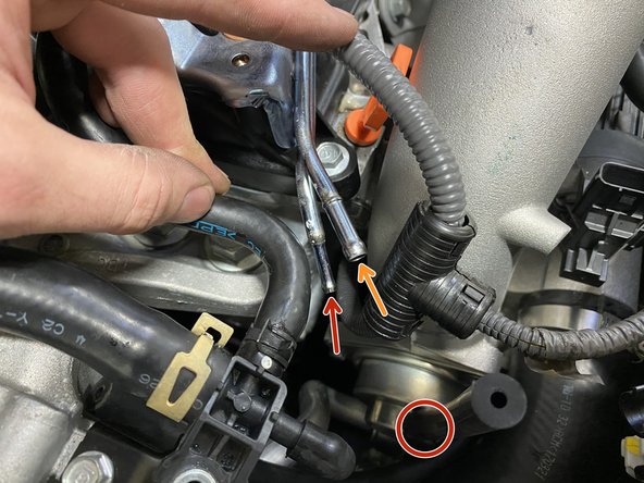
Use pliers to loosen the spring clamps. Slide the spring clamps with red circles towards the center of the hose
-
Pull the BPV hoses off the metal tubes in the direction of the orange arrows
-
-
-
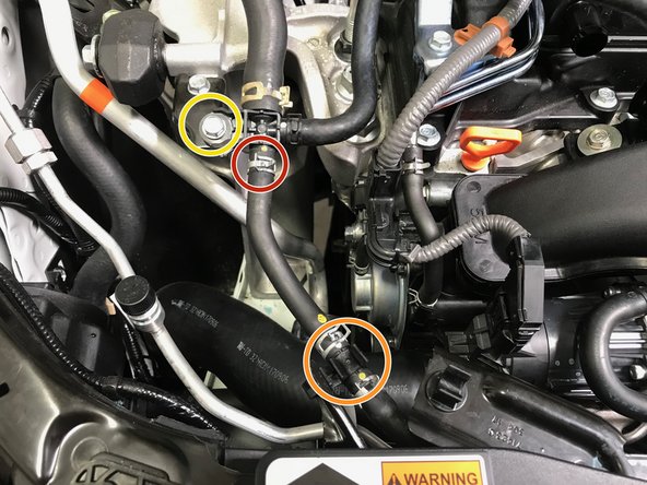
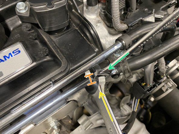
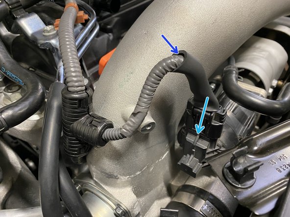
Use pliers to loosen the spring clamp. Slide the clamp towards the center of the of the hose
-
Pop the hose out of the plastic clip
-
Pull the hose off the plastic "T". Move the hose towards the front of the car out of the way
-
Some coolant may spill from the hose and "T" connection
-
Use a 10mm socket & ratchet to remove the bolt holding the "T" connection
-
-
-
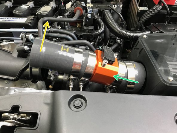
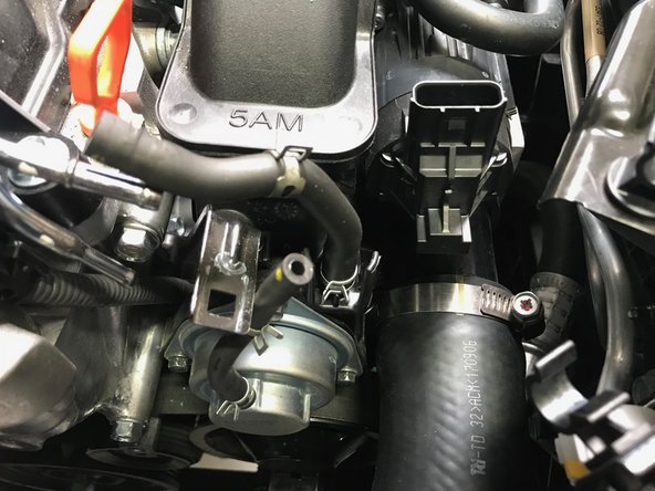
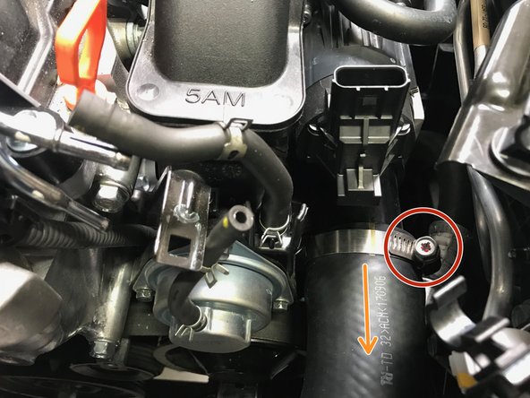
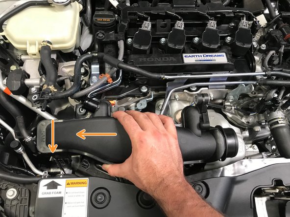
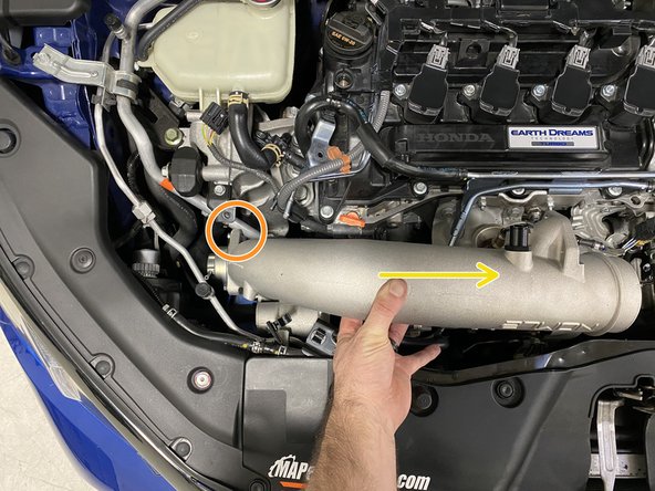
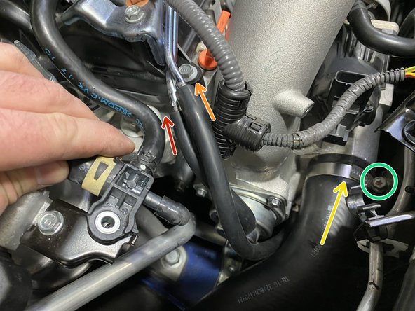
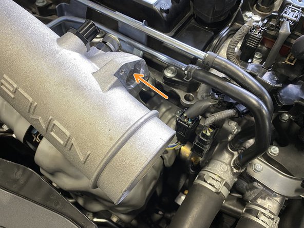
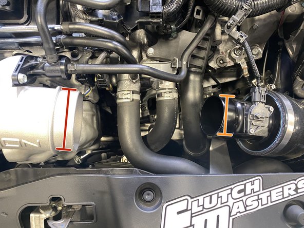
Use a 10mm socket & ratchet or Phillips screwdriver to loosen the worm-gear clamp
-
Pull the hose off the TIP in the direction of the arrow
-
Remove the clamp from the hose so it does not get lost in the engine bay
-
Bend the hose towards the rear of the car. Stuff it into the fender liner out of the way
-
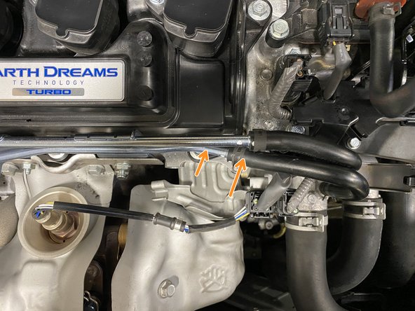
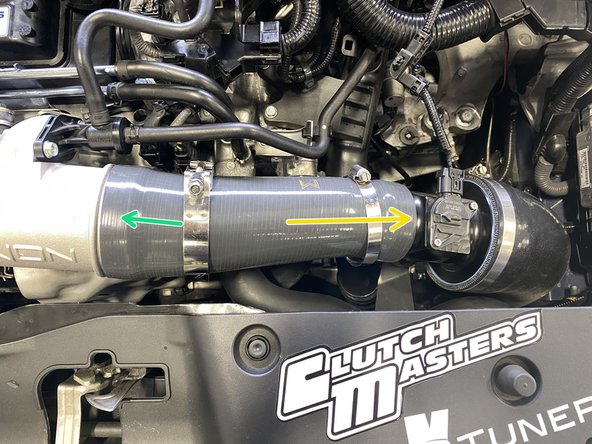
If you have a 27WON intercooler kit you will not be able to bend the silicone hose
-
Instead, press the silicone hose under the silver A/C hard line shown with the arrow
-
-
-
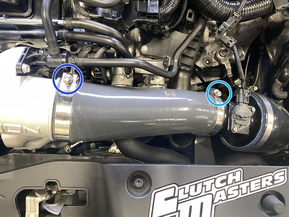
Use a 10mm socket & ratchet to remove the two (2) TIP mounting bolts
-
This mounting bolt will be reused for the installation of the 27WON TIP mounting bracket supplied with the kit.
-
-
-
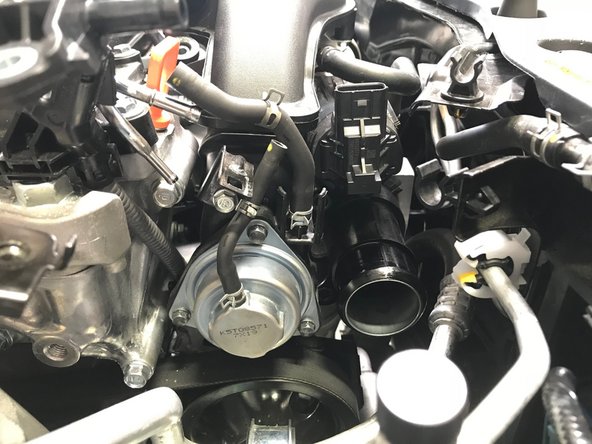
The next process is to remove the Turbo Inlet Pipe (TIP) from the vehicle.
-
We will first identify the hardware location and how to remove without losing the hardware in the engine bay
-
Second, we will show step by step images of physically removing the TIP for PDF users and a quick video for mobile users
-
-
-
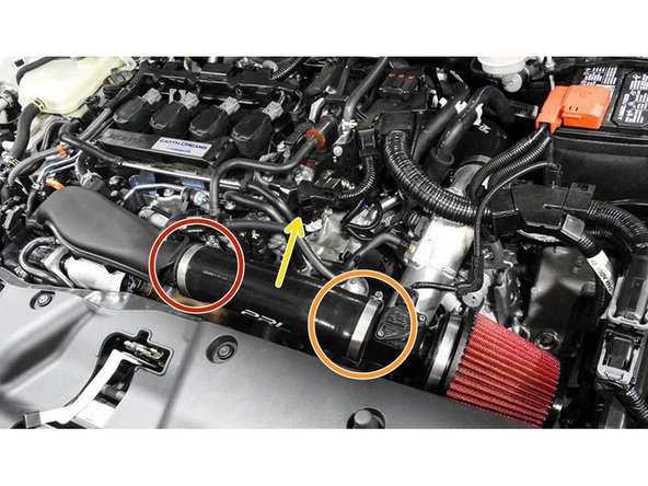
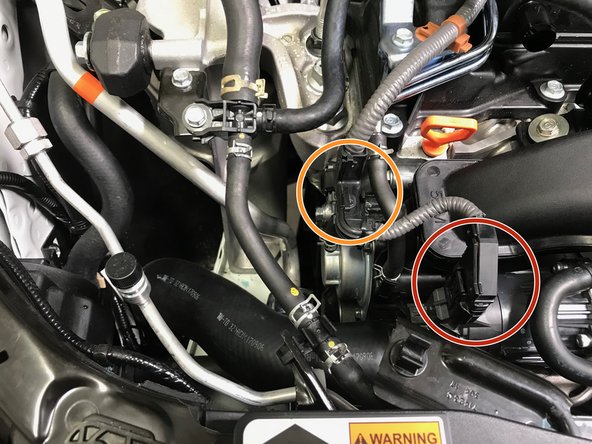
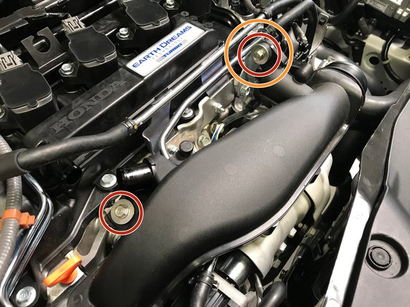
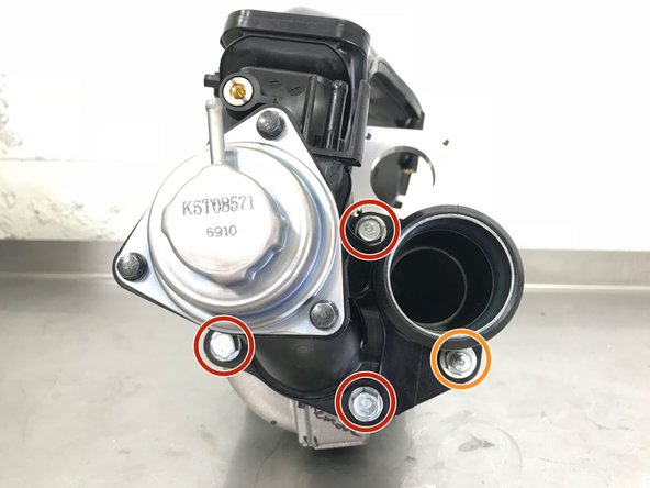
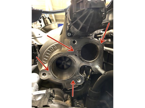
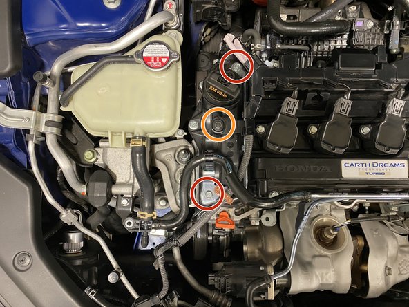
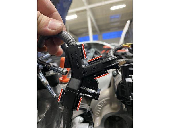
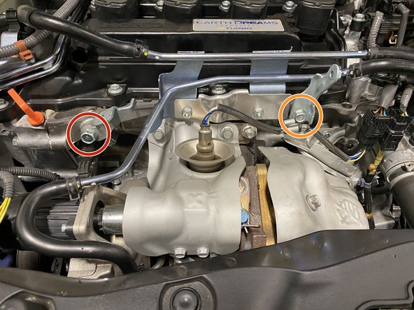
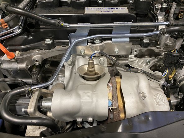
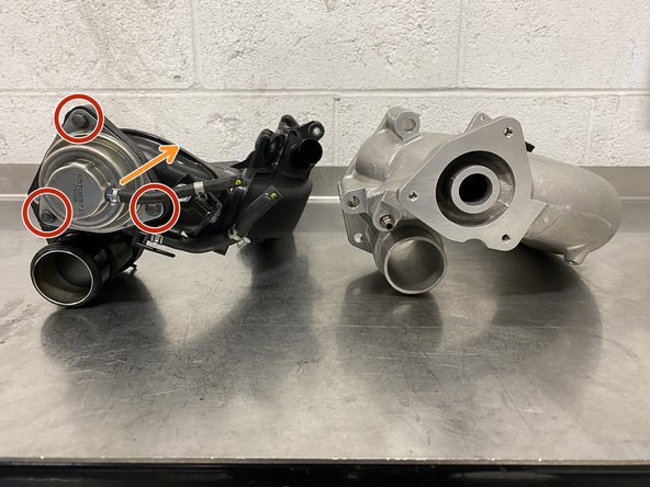
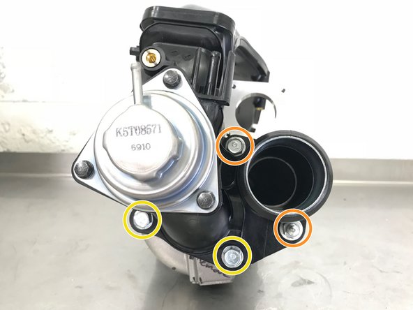
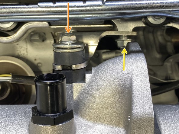
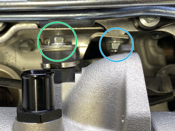
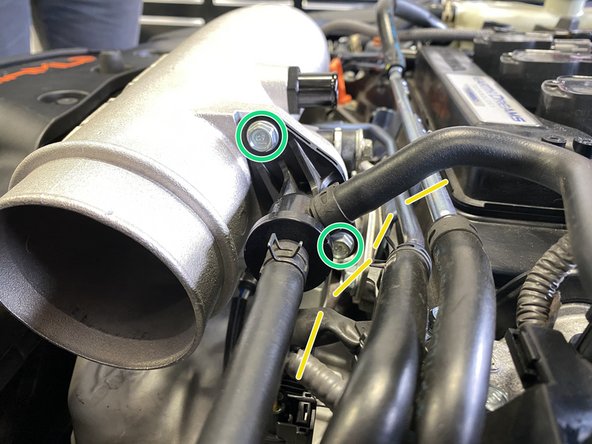
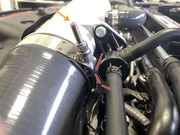
Locating the mounting hardware on the TIP can be difficult. Please see the second image for clear identification
-
The hardware circled in red are bolts. The hardware circled in orange is a nut on a stud
-
Use a 12mm socket, long extension & ratchet to loosen the three (3) bolts
-
Use a 12mm socket, long extension & ratchet to loosen one (1) nut
-
With the bolts loose, but not removed, use the magnet on a stick to remove the bolts from the TIP
-
-
-
Mobile Users proceed to Step 16 for video tutorial
-
Pull the oil dip stick out a couple inches and flex out of way
-
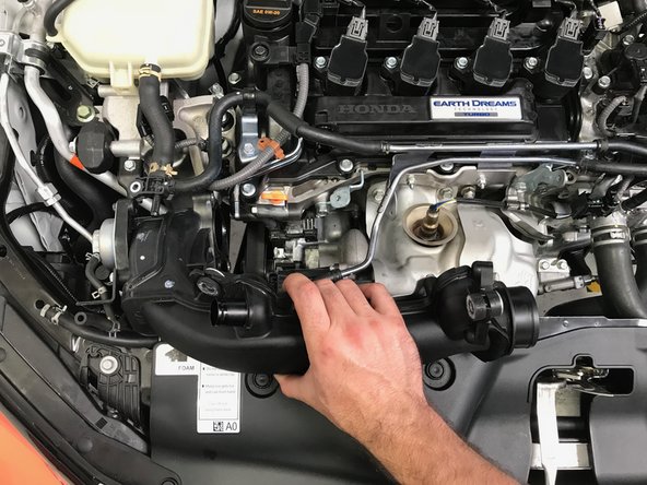
Move the TIP towards the passenger side of the vehicle past the oil dip stick
-
Reinstall the oil dip stick
-
Move the TIP further towards the passenger side of the vehicle and begin to rotate the top of the TIP towards the front of the vehicle
-
Continue the rotation of the TIP while moving the TIP up and out of the engine bay
-
-
-
Pull the oil dip stick out a couple inches and flex out of way
-
Move the TIP towards the passenger side of the vehicle past the oil dip stick
-
Reinstall the oil dip stick
-
Move the TIP further towards the passenger side of the vehicle and begin to rotate the top top of the TIP towards the front of the vehicle
-
Continue the rotation of the TIP while moving the TIP up and out of the engine bay
-
-
-
Using a spray glass cleaner (or equivalent) and rag, clean the surface of the compressor housing face
-
The surface needs to be dry and smooth for a correct gasket sealing surface
-
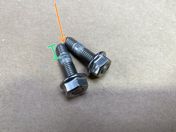
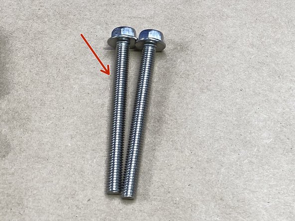
Locate the provided M8 studs
-
The M8 Flange nut comes pre-installed, remove the nuts
-
NOTE: Short end of threads goes into the compressor housing
-
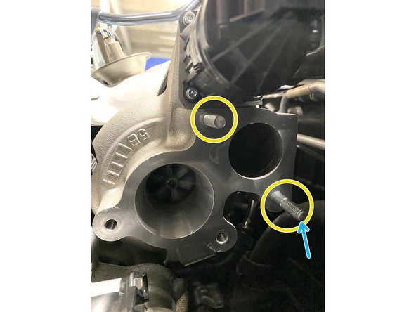
Install the provided M8 stud in the upper location as shown hand tight
-
If you still have the OEM stud, you can use that stud in the lower location
-
Two (2) studs are provided if you are missing the OEM stud
-
-
-
Use a 10mm socket & ratchet to remove the two (2) 10mm bolts
-
Use a 10mm socket & ratchet to remove the one (1) 10mm bolts
-
-
-
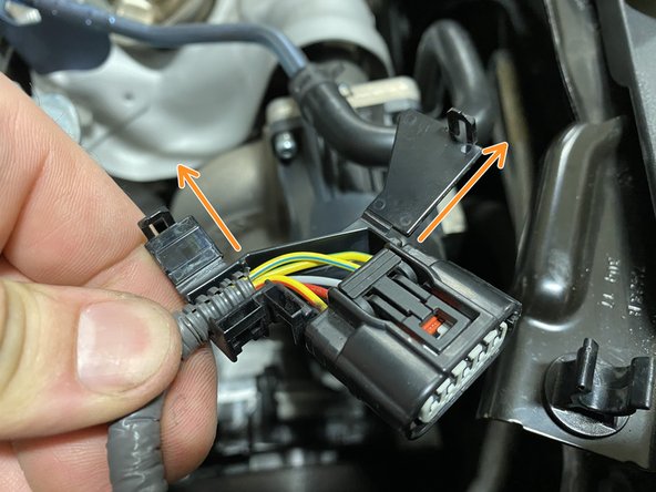
Removing the wiring loom cover is tedious and delicate - take your time so you do not break the covers
-
Using a small flat head screwdriver, pry the tabs out
-
With the tabs slightly pryed out, you can pull the cover flaps up and out as shown
-
-
-
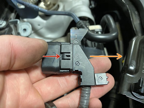
Using a small flat head screwdriver, pry the "loop" tab up
-
With the loop tab loose, slide the cover off
-
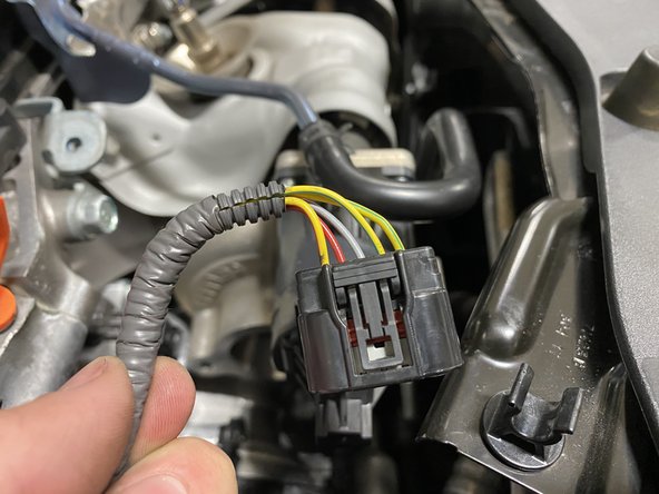
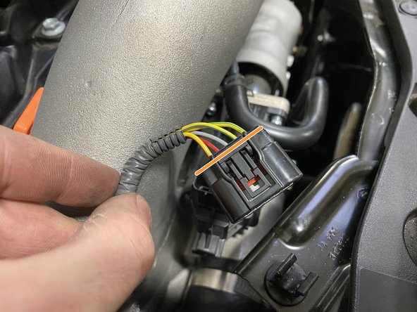
The result is just the wastegate actuator connector and exposed wiring
-
-
-
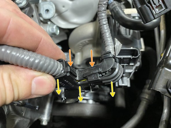
Removing the wiring loom cover is tedious and delicate - take your time so you do not break the covers
-
There are five (5) tabs that need to be loosened to remove the cover from the wiring loom
-
Using a small flat head screwdriver, pry the tabs out
-
Not all tabs are shown
-
As you pry loose tabs, pull the wiring loom cover apart and hold apart
-
The wiring loom cover will try to snap back together if you do not hold it apart while loosening all tabs
-
-
-
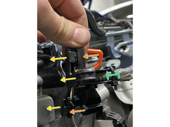
Using a small flat head screwdriver, pry the tabs out
-
Not all tabs are shown
-
As you pry loose tabs, pull the wiring loom cover apart and hold apart
-
The wiring loom cover will try to snap back together if you do not hold it apart while loosening all tabs
-
Cut the zip-tie once the wiring loom is fully opened and ready to remove
-
The result is just the wiring loom "T" location exposed wiring
-
-
-
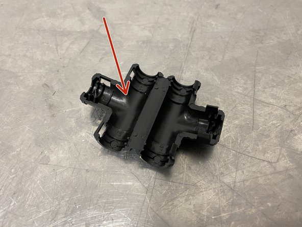
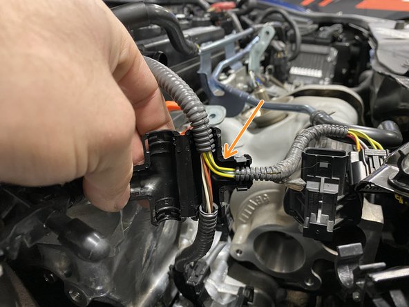
Locate the provided wiring loom T-cover
-
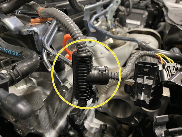
Place the the T-cover over the wiring loom as shown
-
Fold the T-cover closed - it should have a distinct snap when closed and locked
-
-
-
Use a 14mm socket & ratchet to remove the one (1) 14mm bolt and bracket
-
This bracket and bolt is not reused
-
Use a 12mm socket & ratchet to remove the one (1) 12mm bolt and bracket
-
This bolt is reused for the provided 27WON bracket
-
This bracket is not resused
-
-
-
Review Part A and Part B (Next Step) before proceeding
-
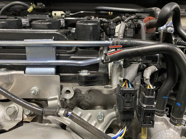
The lower metal coolant pipe needs to be bent down a small amount to provide clearance for the EVAP Valve
-
The location shown with the orange mark is where you will bend the metal pipe
-
Place the open end of a 17mm wrench on the metal pipe at the bend location
-
Place the open end of a 9mm wrench on the 17mm wrench as shown
-
The 9mm wrench will be used to twist the 17mm wrench and bend the pipe
-
While holding the 17mm wrench in your left hand, rotate the 9mm wrench downward
-
Bend the metal pipe down until the lower rubber hose is below the upper rubber hose - shown in next step
-
-
-
See the small gap between the lower and upper rubber hoses - this is the goal
-
Once you have verified the lower metal pipe has been bent down far enough then by hand bend the metal pipe towards the back of the car slightly - it will end up under the upper metal pipe as shown
-
-
-
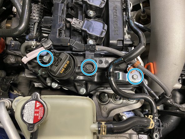
Use a 8mm socket & ratchet to remove the three (3) 8mm bolt
-
Remove the OEM rubber hose from the BPV
-
This hose is not reused
-
Use a 8mm socket & torque wrench to install the three (3) 8mm bolts in the 27WON TIP. Torque to 5-7 ft-lbs
-
Install the longer provided 4mm silicone hose onto the silver hose barb (not shown on TIP)
-
-
-
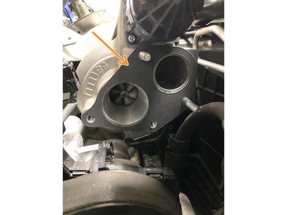
Locate the provided gasket
-
Install the gasket on the compressor face as shown
-
-
-
Installation of the TIP follows the same process for removal in reverse with minor changes due to the size of the 27WON TIP
-
Lower the TIP into the engine bay with the TIP rotated towards the front of the car
-
Rotate and lower the TIP into the engine bay then move it towards the driver's side of the engine bay
-
There will be some interference between the BPV and A/C line while installing
-
Pull the oil dip stick out a couple inches and flex out of way
-
Move the TIP further to the driver's side while sliding the TIP over the two (2) studs in the compressor housing
-
Reinstall the oil dip stick
-
-
-
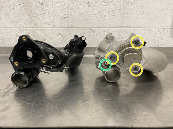
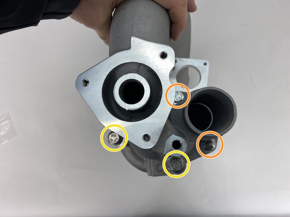
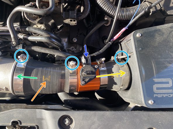
An installed OEM and 27WON TIP is shown out of the car for clarity
-
Locate the provided two (2) M8x80mm flange bolts
-
The two (2) orange circles show the locations of the 13mm flange nuts
-
The two (2) yellow circles show the locations of the provide long 12mm flange bolts
-
Tighten the hardware and torque to 15-19 ft-lbs
-
-
-
Locate the two (2) metal BPV pipes near the TIP as shown
-
In the following instructions - bend the metal pipes in small increments then check clearance
-
Using the closed end of a box-end wrench, thread the metal pipe through the close end then use the wrench to bend the metal pipe
-
Bend the small lower metal pipe away from the TIP as shown - approximately 3/4" clearance is desired
-
Bend the large upper metal pipe away from the TIP as shown - approximately 3/4" clearance is desired
-
Align the bolt hole with the threaded insert in the valve cover then check clearance between the TIP and metal BPV pipes
-
Continue the orange, yellow & green instructions as needed until sufficient clearance is achieved
-
Use a 10mm socket & torque wrench to install the three (3) mounting bolts. Torque to 8-10 ft-lbs
-
-
-
Install the short silicone hose onto the BPV hose barb (red circle)
-
Install the short silicone hose onto the small bent metal pipe (red arrow)
-
Install the long silicone hose onto the large bent metal pipe (orange arrow)
-
The other end is already attached to the TIP at the silver hose barb connection in step 27
-
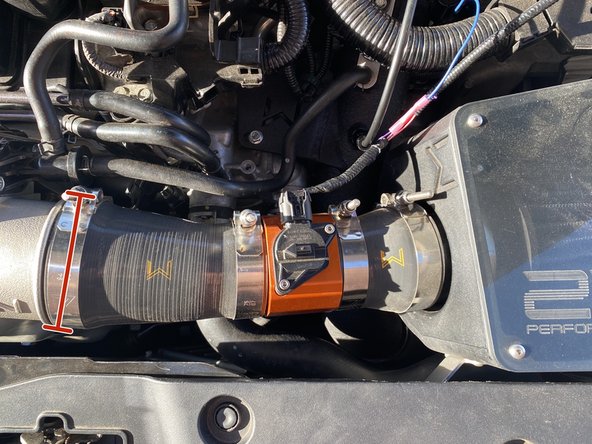
Re-install the intercooler hose onto the TIP as shown
-
Using a 10mm socket & ratchet, tighten the clamp until the intercooler hose bulges slightly
-
-
-
Where gloves and be cautious of where you are directing heat when using a heat gun
-
You do not want to burn or melt any wiring or connections while doing this process
-
Take your time apply just enough heat to constrict the shrink wrap
-
Locate the provided heat shrink wrap section
-
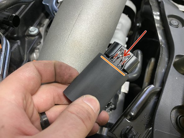
Slide the heat shrink tubing over the WGA connector as shown
-
Align the edge of the heat shrink tubing so that it overlaps the connector slightly as shown
-
Using a heat gun - direct heat to the section closest to the connector to start constricting the shrink wrap around the connector
-
-
-
Where gloves and be cautious of where you are directing heat when using a heat gun
-
You do not want to burn or melt any wiring or connections while doing this process
-
Take your time apply just enough heat to constrict the shrink wrap
-
As the shrink wrap constricts - work your way down the wire to shrink the entire section as shown
-
Connect the wiring to the WGA as shown
-
Apply a little more heat to the end of the shrink wrap if there is a small gap
-
A tiny gap is shown - try to shrink the wrap to this or smaller gap
-
-
-
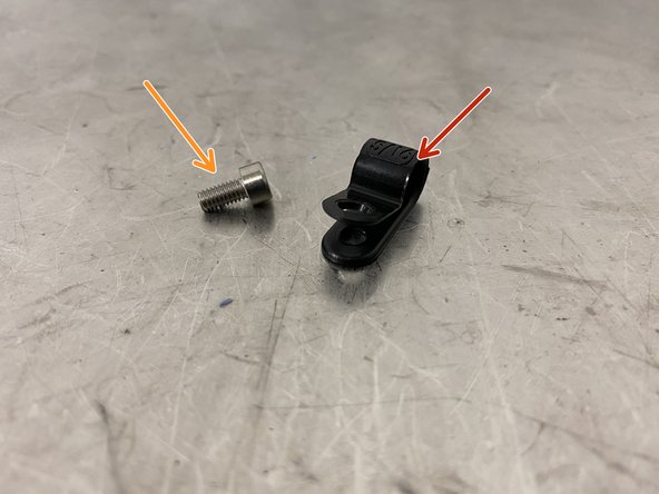
Locate the provided loop clamp
-
The M4 socket cap screw is already install in the turbo inlet pipe
-
Slide the loop clamp over the wiring harness as shown
-
Align the loop clamp mounting hole with the mounting peg on the TIP
-
Using a 3mm Allen key, install M4 socket cap screw into the loop clamp and TIP
-
Tighten until snug - you need very little force here
-
-
-
Use a 10mm socket to install the bolt holding the "T" connection. Torque to 8-10 ft-lbs
-
Pop the hose into the plastic clip
-
Push the hose onto the plastic "T"
-
Use pliers to install the spring clamp at the end of the coolant hose around the "T" connection
-
-
-
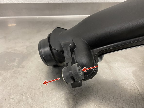
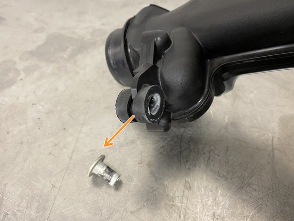
Locate the shown rubber mounting isolator on the OEM TIP
-
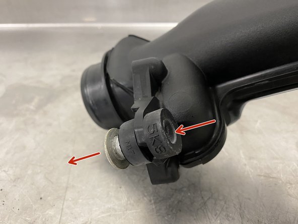
Press the silver metal collar out first
-
Squeeze the rubber isolator and pull out sideways
-
-
-
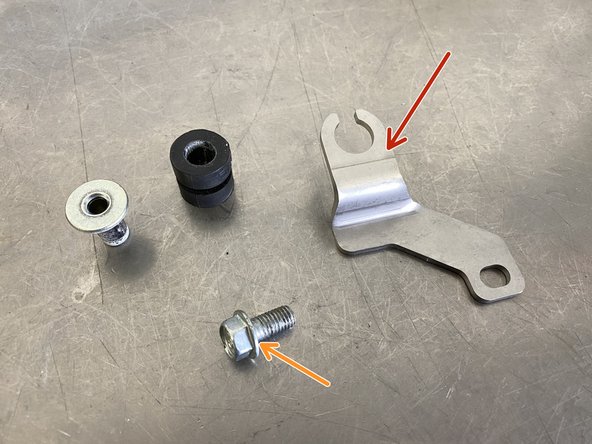
Locate the provided mounting bracket
-
Locate the 12mm OEM bolt that was holding the original mounting bracket
-
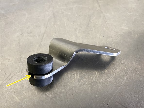
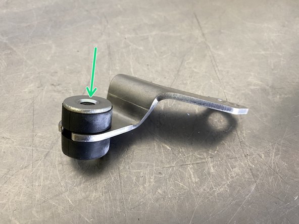
Press in the rubber isolator in the same way it was removed
-
Press in the silver metal collar exactly as shown
-
-
-
Locate the area shown - this is where the mounting bracket will be installed
-
Hand thread the OE TIP bolt through the isolator into the 27WON TIP
-
Hand thread the OE 12mm flange bolt through the bracket into the cylinder head
-
Use a 10mm wrench. Tighten until snug or approximately 8-10 ft-lbs
-
Use a 12mm wrench. Tighten until snug or approximately 12-14 ft-lbs
-
-
-
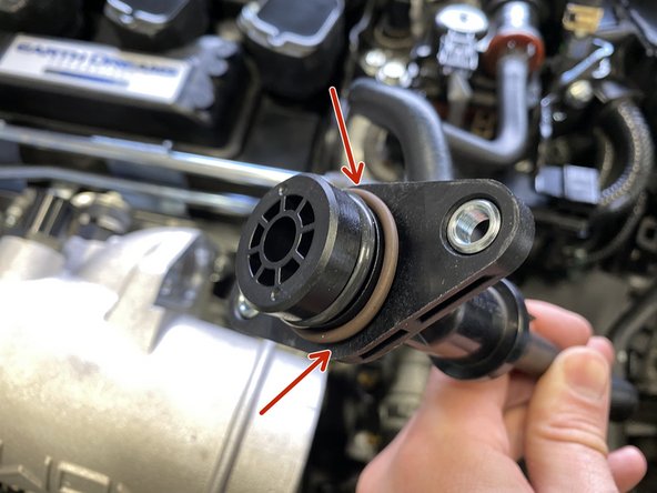
Install the provided brown o-ring over the EVAP valve as shown
-
Verify both o-rings are clean
-
Apply a very light layer of silicone lubricant spray to the brown o-ring
-
Press the EVAP Valve into the turbo inlet pipe
-
Verify the EVAP Valve or hoses are not rubbing on anything
-
Use a 10mm socket & torque wrench to install the two (2) 10mm bolts. Torque to 8-10 ft-lbs
-
-
-
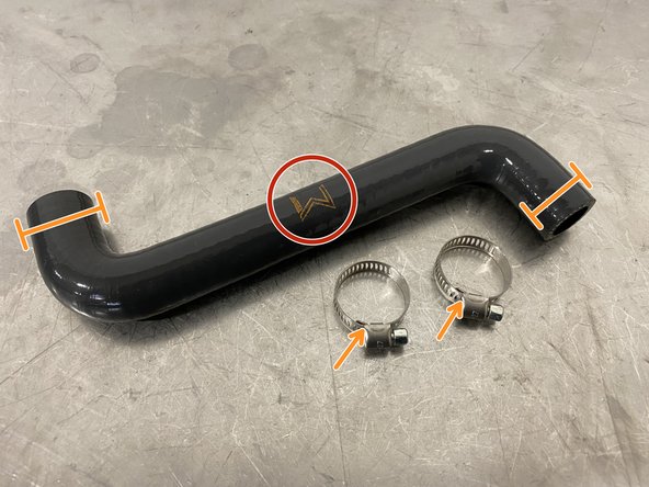
Locate the 27WON valve cover breather hose - the "W" should be facing the front of the vehicle when installed
-
Place QTY(1) worm gear clamp on each end of the silicone hose
-
Push the hose onto the valve cover first
-
Push the hose onto the black hose barb on the turbo inlet pipe second
-
Use a flat head screwdriver to tighten the worm gear clamps - tighten until the silicone bulges slightly
-
-
-
This step is provided before you install your intake system so that you are aware and do not have to redo work
-
Failure position the T-Bolt clamp as shown may damage the hood
-
For all intake fitment options - verify the provide T-bolt clamp is position as shown
-
There should be clearance between the EVAP Valve and the T-bolt clamp as shown
-
If the T-bolt clamp is rotated forward (CCW in image) too far it may contact the hood
-
-
-
Due to the design and pursuit for peak performance, the 27WON Turbo Inlet Pipe does not fit exactly like OEM. To provide you with the easiest & best possible fitment, we have developed silicone couplers to fit the common intake systems currently available
-
For Intake Installation:
-
Step 44 for 27WON Intake Systems
-
Step 45 for PRL Intake Systems
-
Step 46 for Generic 2.5" Pipe Intake Systems
-
-
-
The provided 27WON T-Bolt Clamp will be used on the TIP
-
Replace the TIP side silicone with the new provided 27WON silicone
-
Slide the MAF/Silicone assembly onto the airbox first
-
Then slide the MAF/Silicone assembly onto the TIP
-
Rotate the new TIP coupler until both the MAF housing and TIP have good fitment
-
Using a 10mm socket and ratchet, tighten the T-bolt clamps until the silicone bulges slightly
-
Connect the wiring harness to the MAF sensor
-
-
-
The provided 27WON T-Bolt Clamp will be used on the TIP
-
The clamp that originally came installed on the PRL intake will be used on the MAF housing
-
Place the clamps on the 27WON coupler before installing on the vehicle
-
Slide the silicone coupler onto the MAF housing first
-
Slide the silicone coupler onto the TIP next
-
Rotate the coupler until both the MAF housing and TIP have good fitment
-
Using a flathead screwdriver, tighten the band clamp until the silicone bulges slightly
-
Using a 10mm socket and ratchet, tighten the T-bolt clamp until the silicone bulges slightly
-
-
-
Generic fitment has not been confirmed as of writing these instructions. Installation will be similar to the previous examples.
-
If you have received a 27WON Turbo Inlet Pipe for an intake besides 27WON or PRL please give us a call.
-
-
-
Given the unique and artisan nature of the 27WON Turbo Inlet Pipe, we hope we were able to REDEFINE your experience and expectations of the aftermarket.
-
Every turbo inlet pipe has been cast in aluminum and and hand finished to guarantee quality and superior fitment.
-
If you have received a 27WON Turbo Inlet Pipe that you feel does not live up to the high standard 27WON strives for, then please give us a call. We want to hear your feedback and get you setup with the quality you expect. Thank You
-
-
-
Using genuine Honda coolant, fill the coolant reservoir to MAX
-
A larger performance turbo inlet pipe will create more pronounced turbo induction noises, your gas mileage may drop significantly for the first few tanks from you constantly wanting to hear the turbo spool
-
To get the best performance from your Turbo Inlet Pipe, we highly recommend a custom tune
-
A custom tune for your specific vehicle with your specific modifications will provide the best performance for your Civic and the location you live in
-
-
-
This completes the installation of your 27WON Performance Turbo Inlet Pipe
-
We hope you were impressed with your 27WON experience and love your new W1 Turbo for years to come. Email us at sales@27won.com or call us at 571-271-0271 with any questions or concerns
-
Please Leave a review here: https://store.27won.com/10th-gen-civic-t...
-
Share your experience using #27WON on Instagram and Facebook
-