Introduction
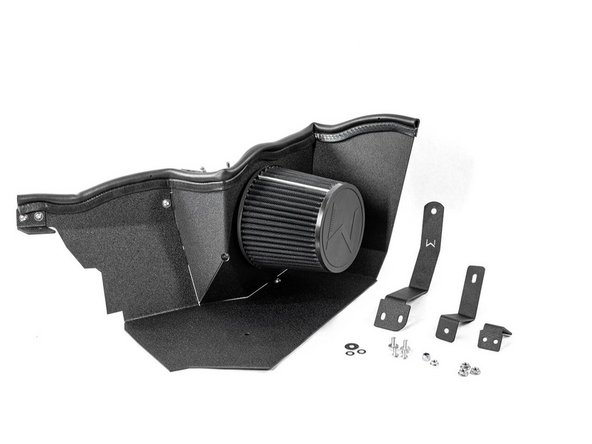
In this installation guide we have provided step by step instructions to remove the OEM intake then install the 27WON Hybrid Intake.
Advisory:
- Working under the vehicle requires a safe and sturdy location for the vehicle to sit on jackstands
- The engine will be hot after recent vehicle operation. Allow the vehicle to cool or use a fan to cool the engine bay before working on the vehicle
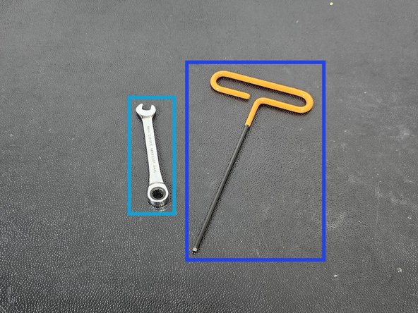
Tools
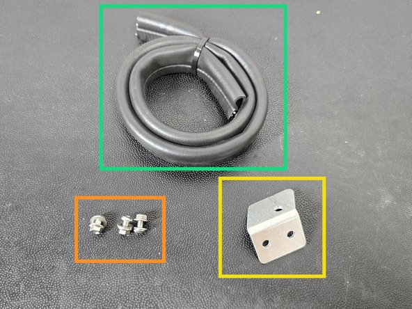
Parts
- Intake Shroud, 2 pieces
- FL5 MAF Housing
- FL5 Intake Bracket × 4
- Silicone Coupler - MAF to Air Filter
- 29" Weather Stripping Seal
- M6x1.0x45mm Hex Head Bolt
- M6x1.0x12mm Flange Bolts × 2
- M6x1.0 Flanged Nuts × 3
- M6x14mm Washer × 2
- M6 Penny Washer
- Assembled M5 Hardware × 5
- ECU Bracket Spacer
- MAF Housing O-Ring
- T-Bolt Clamp - 92-100mm
- T-Bolt Clamp - 102-110mm
- T-Bolt Clamp - 108-116mm
-
-
First and foremost; THANK YOU for becoming a part of the 27WON Family. We hope to REDEFINE your experience of the aftermarket with the highest level Parts, Customer Service, Packaging, & Support
-
This guide describes a process to install your new Hybrid Cold Air Intake into a FL5 Type-R or DE5 Type-S. FL5 install is shown here
-
DE5 Integra installation requires removal of the under hood insulation. It can be reinstalled later but not with 27WON intake
-
-
-
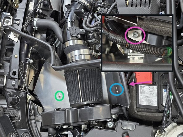
Open the hood to gain access to the intake air box
-
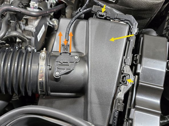
Unplug the connector for MAF sensor by using your fingers to press down on the plastic clip and pulling the plug away from the airbox as shown
-
Using your finger press the two tabs shown towards the airbox, and lift on the wire loom to disconnect the loom from the airbox lid
-
Set the MAF sensor wire out of the way
-
-
-
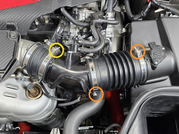
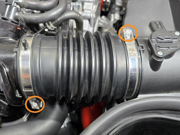
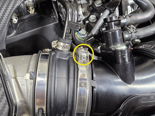
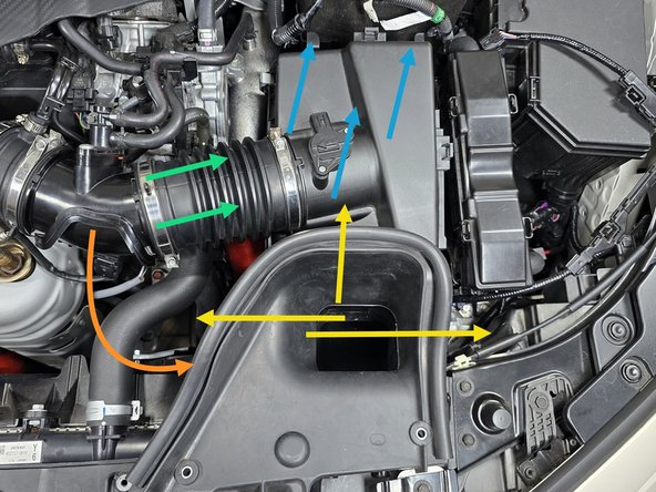
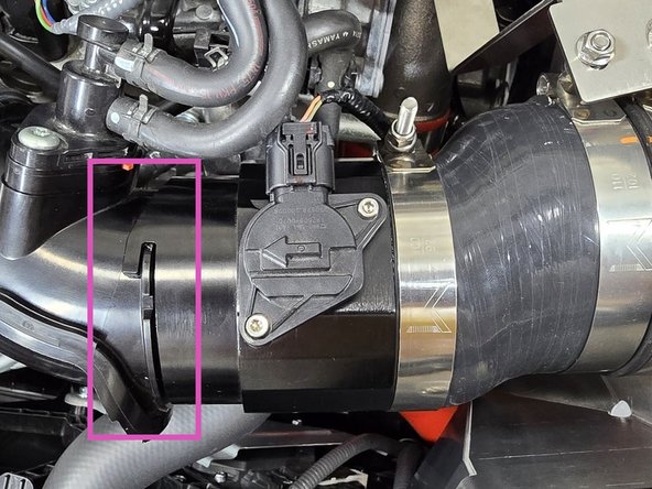
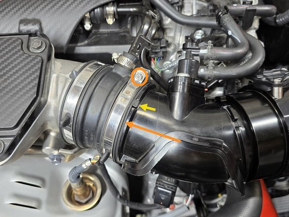
Use a 5.5mm socket and 3/8" ratchet or a small Phillips screwdriver to loosen the two intake clamps circled in orange
-
Use a 5.5mm socket and 3/8" ratchet or a small Phillips screwdriver to loosen the one EVAP elbow clamp circled in yellow
-
-
-
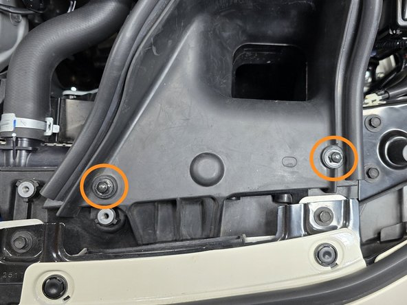
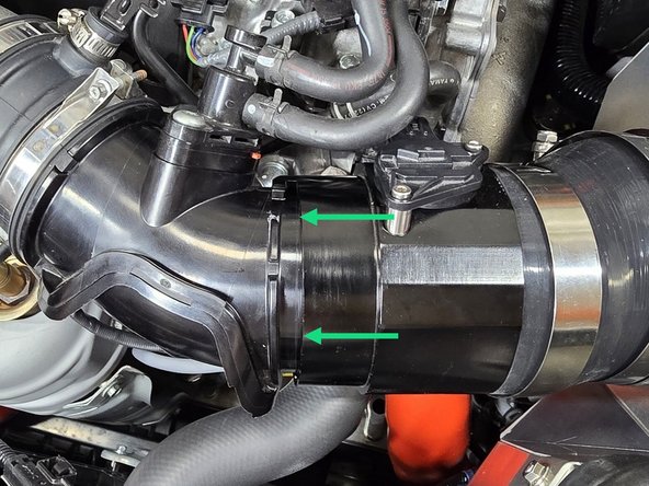
Use a 3/8" drive ratchet and a 10mm socket to remove two (2) bolts that hold the intake duct in place
-
Using your hand pull the rubber end of the duct out of its slot in the radiator shroud
-
This may take a bit of force the first time it comes out
-
-
-
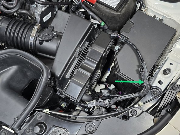
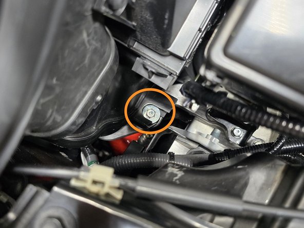
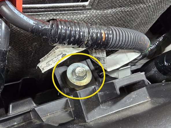
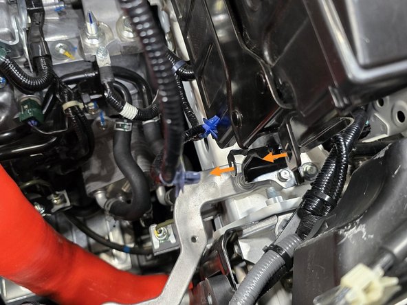
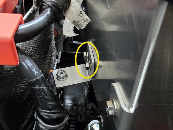
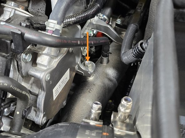
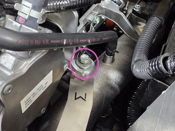
Use a 3/8" rachet, a long extension, and a 10mm socket to remove lower intake bolt
-
Use a 3/8" rachet, a long extension, and a 10mm socket to remove the upper battery bracket bolt
-
-
-
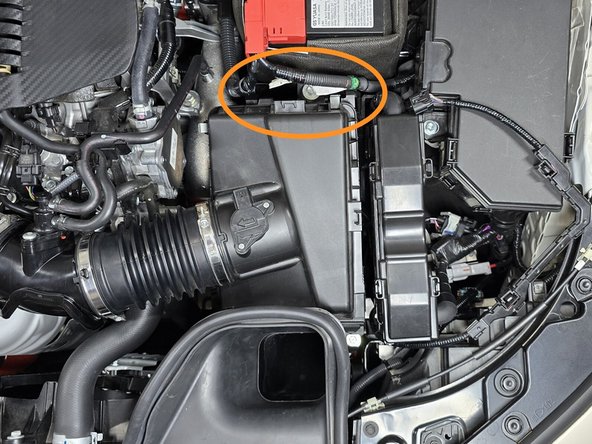
Locate the two positive battery cables that need to be freed from the upper airbox in order to remove the airbox
-
Using your fingers or a pair of needle nose pliers pinch the two battery cable clips and push them out of the airbox bracket
-
Only one side is shown, the other side is the same process
-
-
-
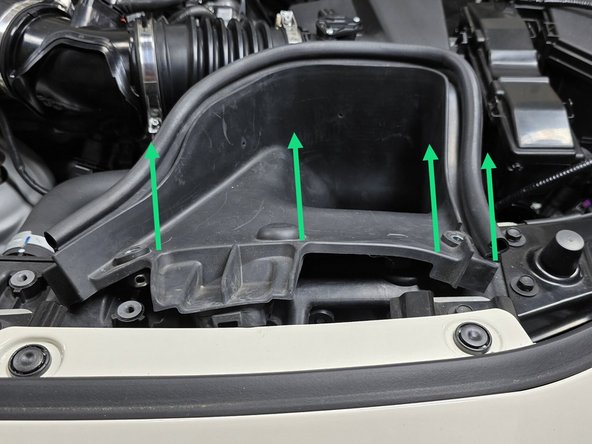
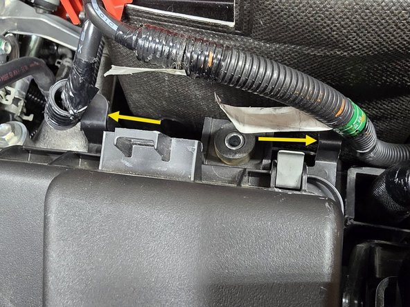
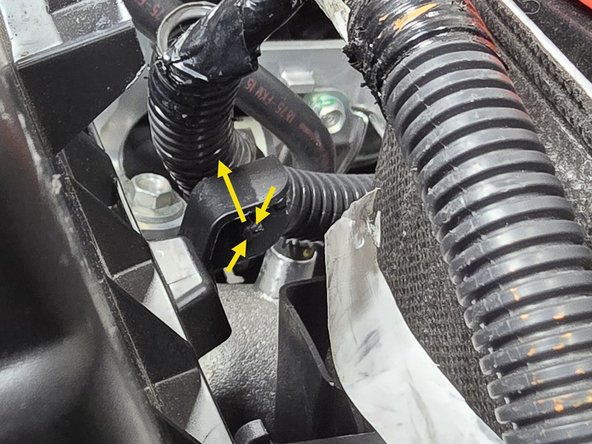
The airbox is still connected to the chassis with a rubber grommet and stud underneath the intake inlet in the area shown
-
Wiggle the inlet back and forth while lifting on the entire airbox to get it loose from the grommet as shown
-
The rubber grommet itself can be left on the mounting stud in the engine bay, or stored with your OE airbox as it will not be used in this install
-
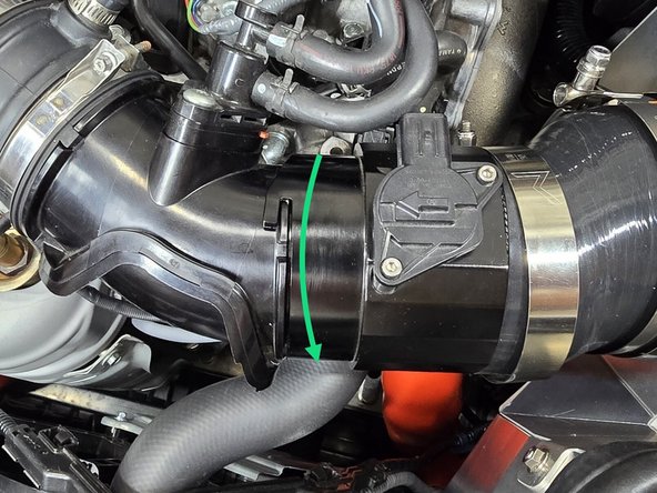
Using your hand pull the accordion intake tube off of the hard plastic EVAP elbow as shown
-
With the intake tube now freed, pull the airbox assembly out of the engine bay
-
Remove the EVAP elbow from the TIP ducting and set aside as shown
-
If you're worried about damaging your engine cover, place a rag down in between the EVAP elbow and the cover
-
-
-
Using your hand or a pair of pliers pinch the top and bottom of the plastic clips holding the MAF loom to the ECU and push them out of the bracket as shown
-
The underside of the bottom clip can be a PITA to reach, using a tool with a hook, like a 45 degree pick, can make this much easier
-
Set the loom off to the side as shown
-
-
-
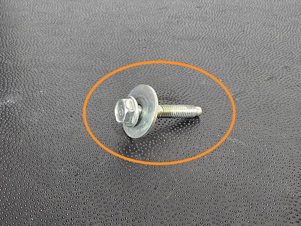
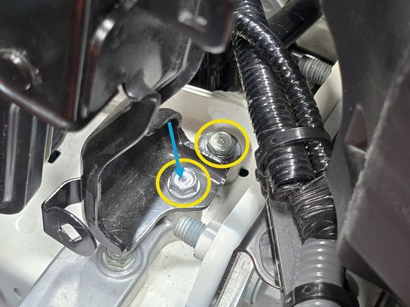
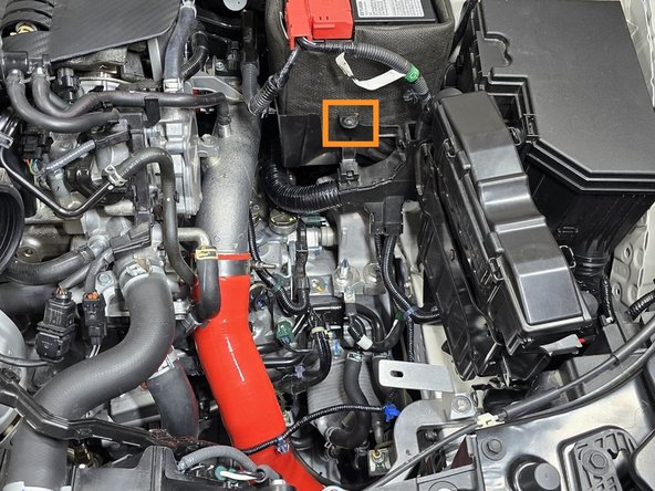
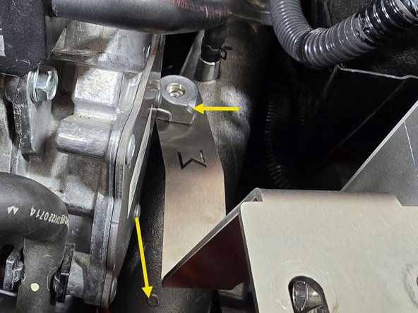
For the ECU relocation you will need one of the 40mm bolts from the OE airbox shown circled in orange
-
This will come from the upper or lower airbox mounting bushing from Step 5
-
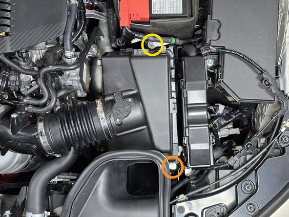
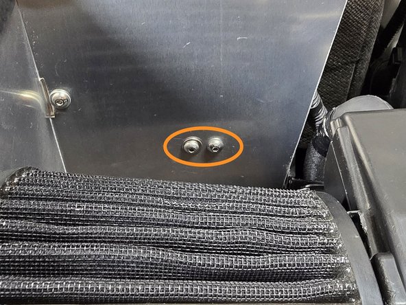
Using a 10mm socket, a long extension, and a 3/8" drive ratchet remove the two 10mm bolts shown circled in yellow
-
Set the M6 20mm bolt with the blue arrow aside for use later in the install
-
-
-
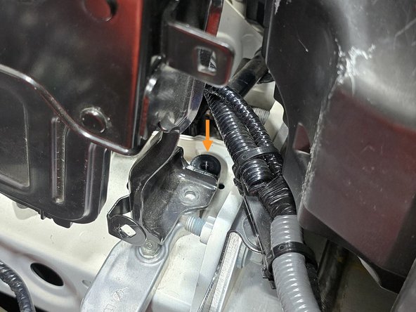
With the bolts removed, place the provided black spacer over the hole closest to the drivers side as shown
-
Move the ECU mounting bracket onto the spacer as shown
-
Hand thread the 40mm bolt through the ECU bracket and spacer as shown
-
Using a 10mm socket a long extension, and a 3/8" drive ratchet tighten down the bolt
-
-
-
You will need the following to prepare the airbox for install:
-
29 inches of the provided vertical bulb trim seal (weather stripping)
-
QTY(3) Assembled M5 hardware
-
QTY(1) Airbox inlet bracket
-
For tools you will need the following:
-
8mm Wrench
-
3mm T-Handle hex wrench provided
-
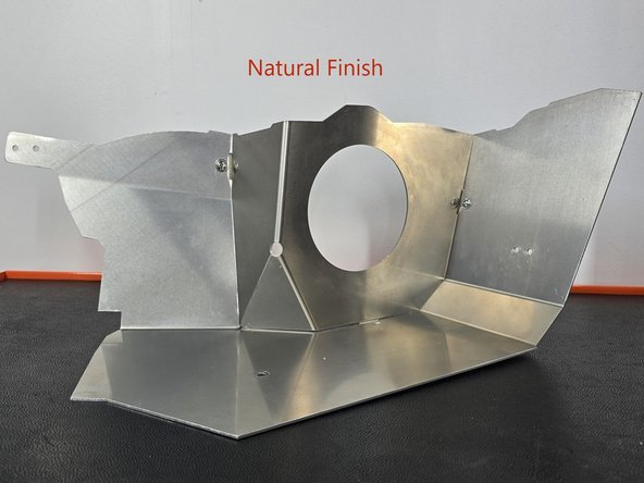
This process is shown with a raw finish shroud, the process is identical for a powder coated shroud
-
-
-
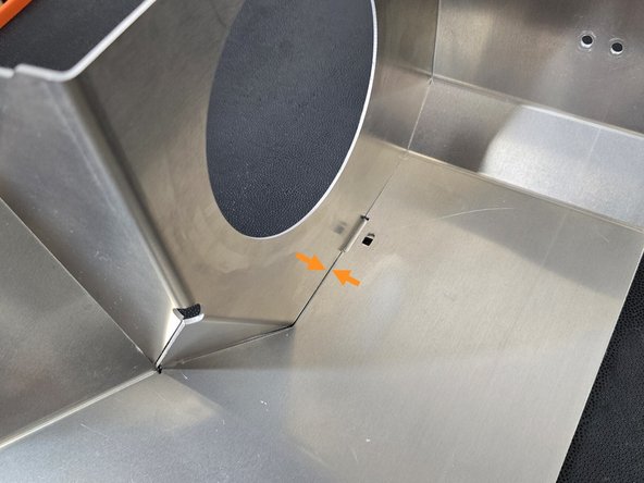
Press the two pieces of shroud together until the gap is minimal
-
Push the provided M5 socket bolt through the provided washer, and two heat shields as shown
-
Thread a proved M5 nut onto the bottom side of the bolt as shown
-
Using a 3mm hex wrench and a 8mm wrench tighten the hardware shown
-
-
-
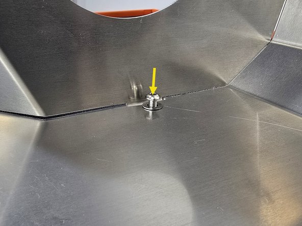
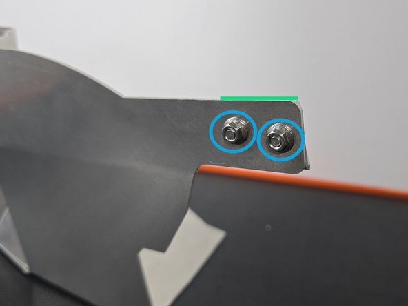
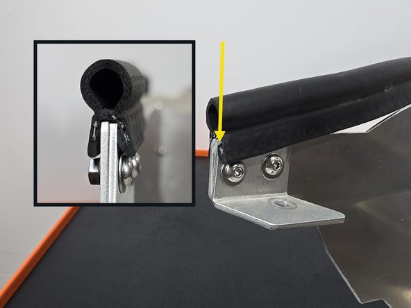
The inlet bracket will mount in the location shown
-
Using the provided M5 hardware secure the inlet bracket as shown
-
The top of the bracket should be flush with the top of the shroud
-
Using a 3mm Allen key, and an 8mm wrench tighten down the hardware as shown
-
-
-
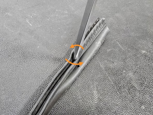
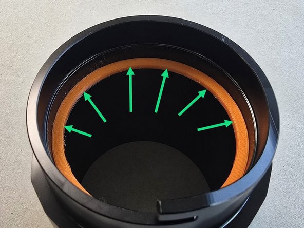
Installing the weather stripping is difficult on the corners. If you run into trouble getting it to set all the way down on the shroud, use a flat head screw driver to spread the mounting seal as shown
-
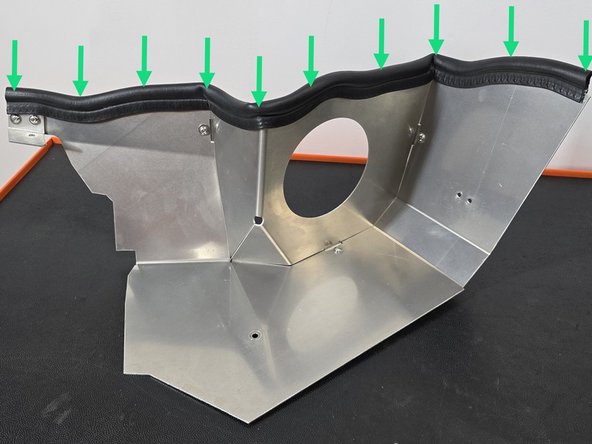
Starting at the inlet bracket (yellow arrow) press the weather stripping over the shroud as shown
-
It is important for the weather stripping to be fully set onto the shroud to ensure your weather stripping does not incur damage, or wear prematurely
-
Press the weather stripping down along the entire rest of the top edge of the shroud as shown
-
The corners will likely give you the most trouble, if you aren't able to seat them fully try the trick from the first bullet
-
-
-
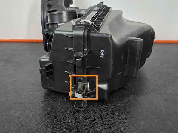
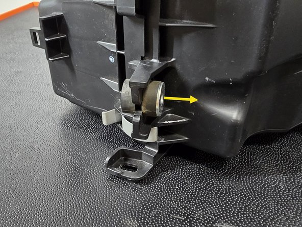
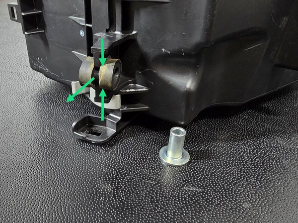
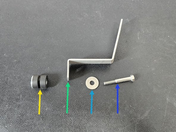
You will need the rubber spacer from the OE airbox for mounting the lower airbox bracket
-
Remove the metal sleeve in the center of the rubber spacer as shown
-
Pinch and remove the rubber spacer as shown
-
With the rubber spacer out of the airbox, reinsert the metal sleeve into the rubber spacer
-
-
-
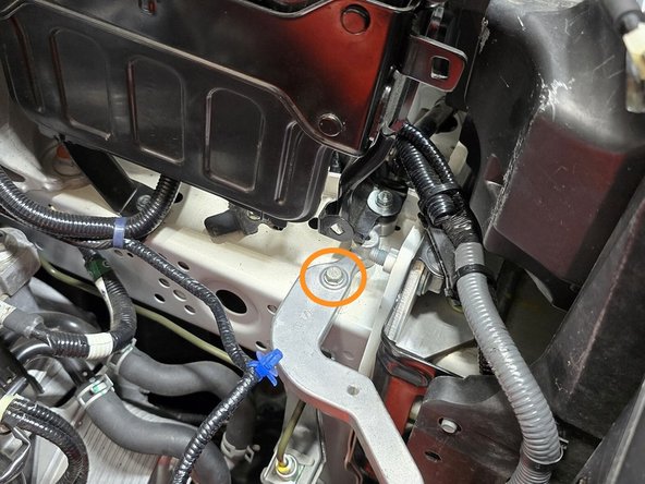
Using a 10mm socket, a long extension, and a 3/8" drive ratchet remove the 10mm bolt shown
-
The lower airbox bracket will mount in the order shown
-
Rubber spacer taken from OE airbox
-
Provided lower airbox bracket
-
Provided M6 penny washer
-
Provided M6 45mm bolt
-
Using a 10mm socket, a long extension, and a 3/8" drive ratchet secure the lower bracket stack up as shown
-
This does not need to be super tight, as the bracket may need to be moved around later in the install
-
-
-
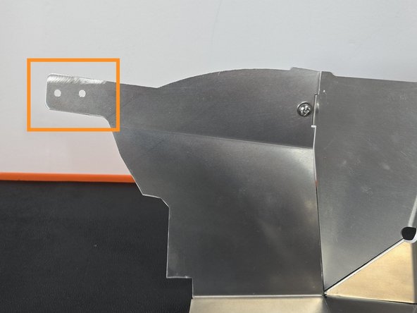
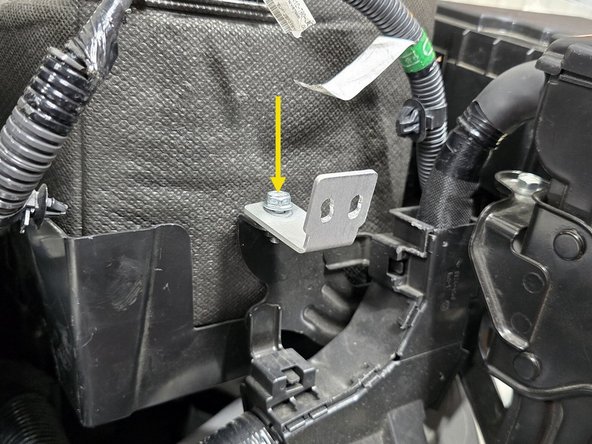
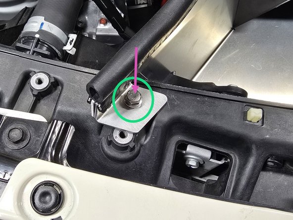
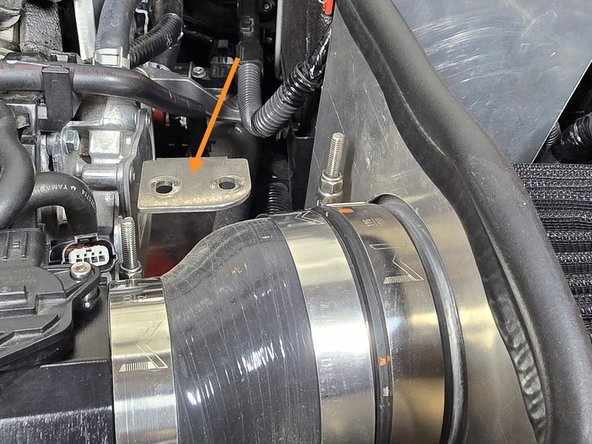
The battery bracket will mount in the location shown
-
Using the 20mm bolt previously securing the ECU mounting bracket, secure the upper battery bracket in the location shown
-
This bracket should be left hand tight as it will need to move around later in the install
-
-
-
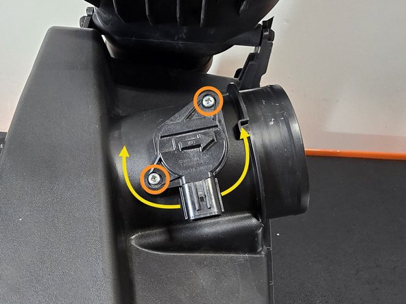
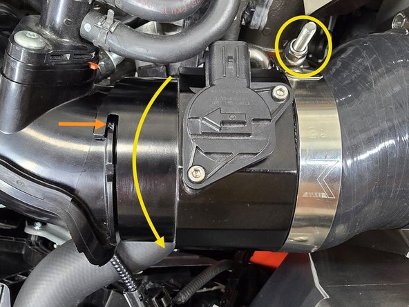
Using a philips head screw driver remove the two screws holding the MAF sensor into the OE airbox
-
Rotate the MAF sensor back and forth to remove it from the OE airbox
-
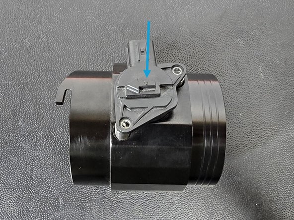
Remove the 3mm provided cap screws from the 27Won MAF housing using the provided T-handle hex wrench
-
Install the MAF sensor into the new housing in the orientation shown
-
You may need to wiggle the sensor back and forth to get it to fully seat, be careful not to break the o-ring!
-
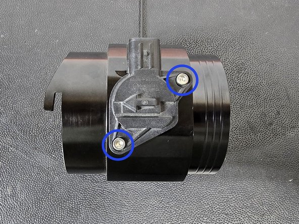
Using a 3mm Allen key and the provided cap screws, secure the MAF sensor as shown
-
-
-
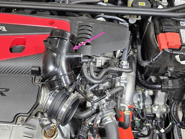
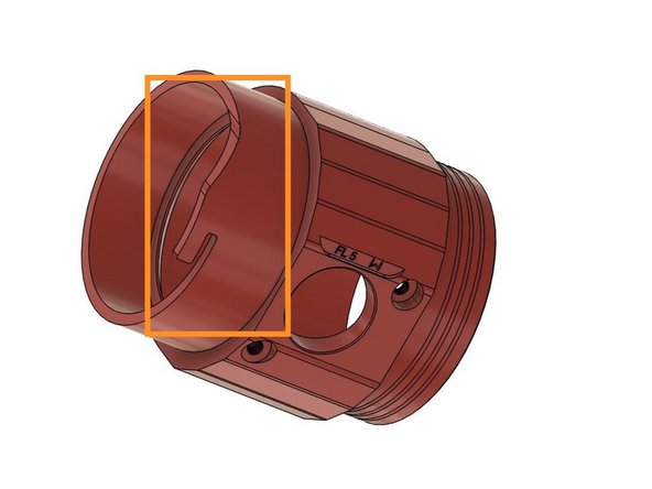
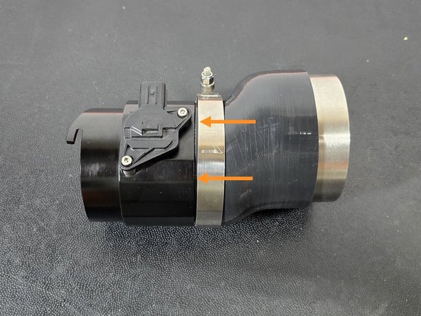
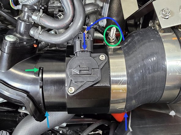
The FL5/DE5 MAF housing has a unique "twist lock" feature instead of a traditional silicone/rubber coupler
-
The FL5/DE5 MAF housing also features a pre installed gasket that makes contact with the EVAP elbow to ensure a solid seal with no leaks!
-
When this gasket is brand new it can make installation a bit of a pain. Don't be afraid to use some force to press the MAF housing and EVAP elbow together!
-
As you can see in the third image, the "hook" on the MAF housing will twist over the ring around the EVAP elbow locking it into place
-
-
-
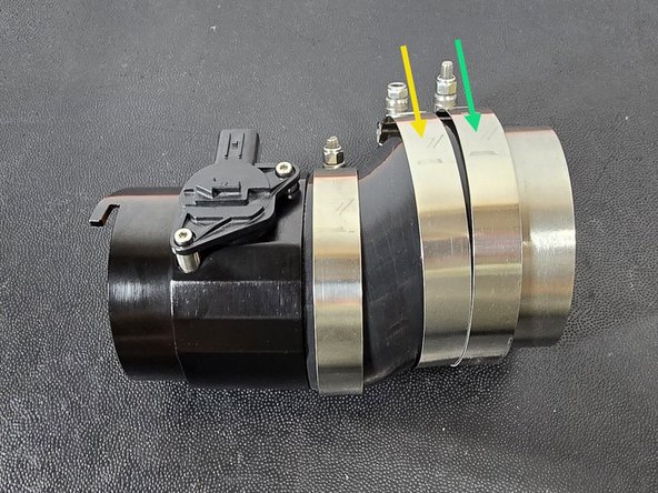
Install the filter silicone onto the MAF housing with the 92-100mm clamp over the silicone as shown
-
Leave the clamp loose, as you will likely need to rotate the silicone during install
-
Place the following clamps over the silicone in the order shown
-
102-110mm
-
108-116mm
-
Put the air filter through the hole in the shroud as shown
-
Insert the stainless steel pipe into the air filter as shown
-
Notice the rotation of the silicone compared to the MAF, you may still need to rotate the silicone for final install, but this is close
-
-
-
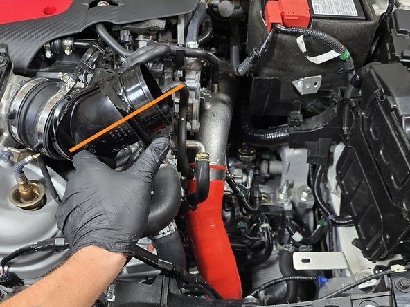
The EVAP elbow will need to be held at this angle for the intake to install easily
-
Partially lower the intake assembly into the engine bay
-
Holding the EVAP elbow in one hand, and the intake in the other, gently press the elbow into the TIP coupler while pressing the MAF housing over the EVAP elbow
-
All these components will be secured later, the focus right now is getting the intake assembly close to it's final position in the engine bay
-
While pressing together the various components, the entire intake should now go lower into the engine bay as shown
-
This is not the final resting place for the intake. Later you will need to adjust the silicone to ensure everything sits properly in the engine bay
-
If the air filter is making contact with the ECU you can tighten the drivers side ECU mounting bolt to compress the included black spacer and pull the ECU away from the intake
-
-
-
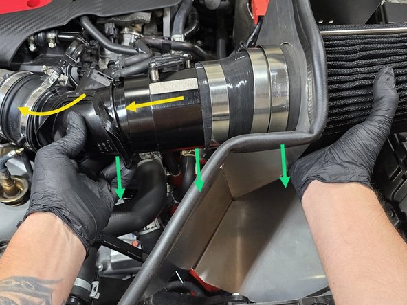
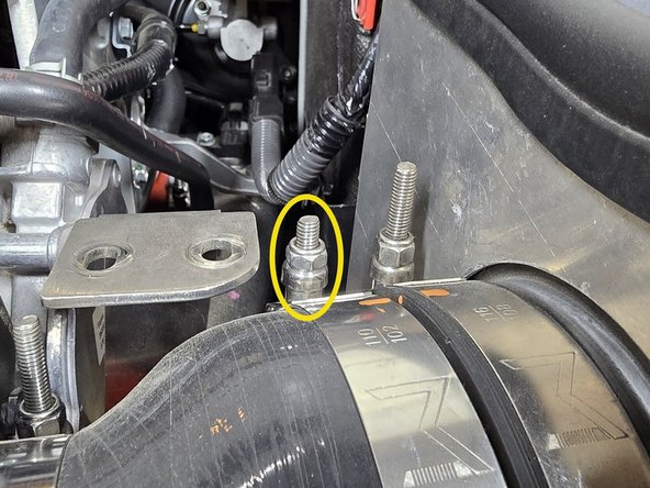
While pressing the EVAP elbow into the TIP coupler, use a 5.5mm socket and 3/8" ratchet or a small Phillips screwdriver to tighten the OE clamp as shown
-
Ensure the small rubber tab aligns with the cut out on the EVAP elbow
-
Press the MAF housing onto the EVAP elbow, then twist it towards the front of the car to lock it in
-
This may take some force on the first install, the gasket inside of the MAF housing is slightly oversized to ensure a secure fit
-
-
-
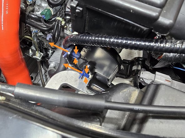
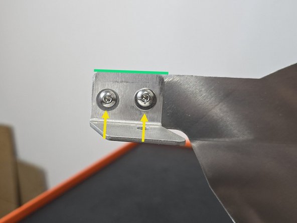
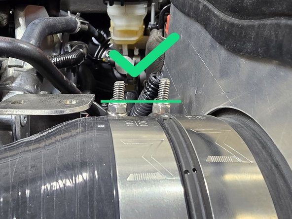
Press the provided M5 cap head bolts through the shroud and upper battery bracket as shown
-
Hand thread the two provided M5 flange nuts onto the bolts as shown
-
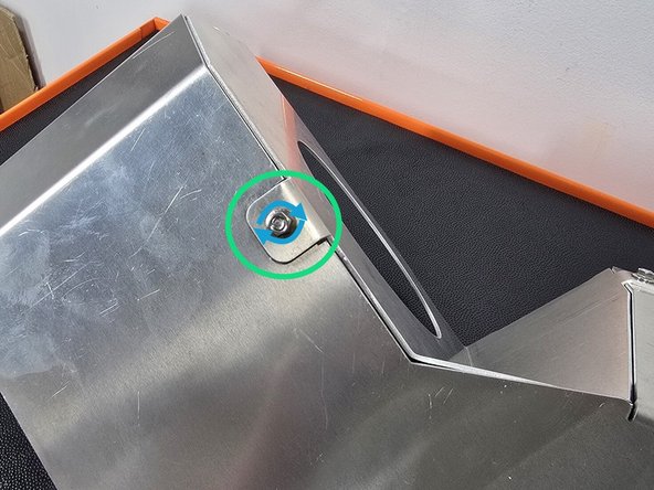
Hand thread the provided 12mm flange bolt through the inlet bracket into the threaded hole shown
-
Using a 10mm socket and a 3/8" drive ratchet secure the inlet bracket
-
-
-
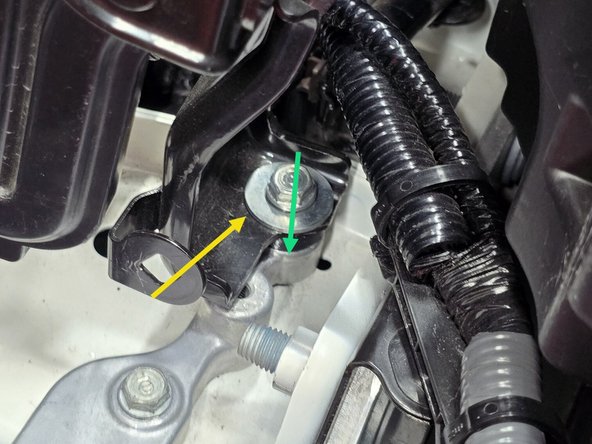
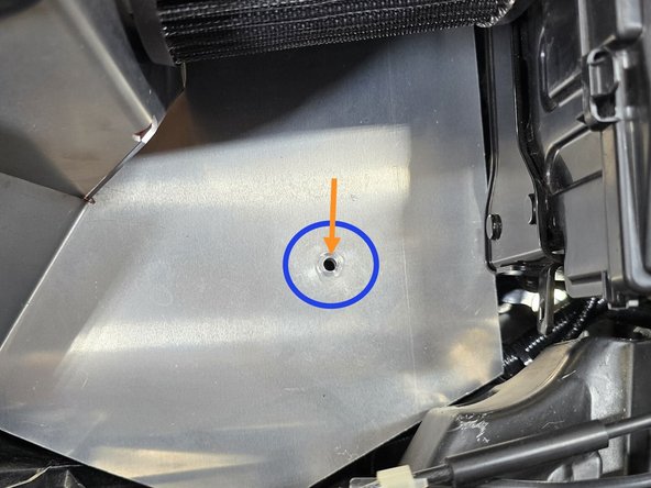
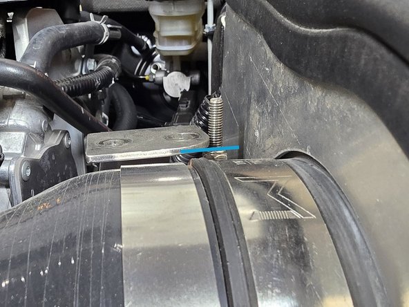
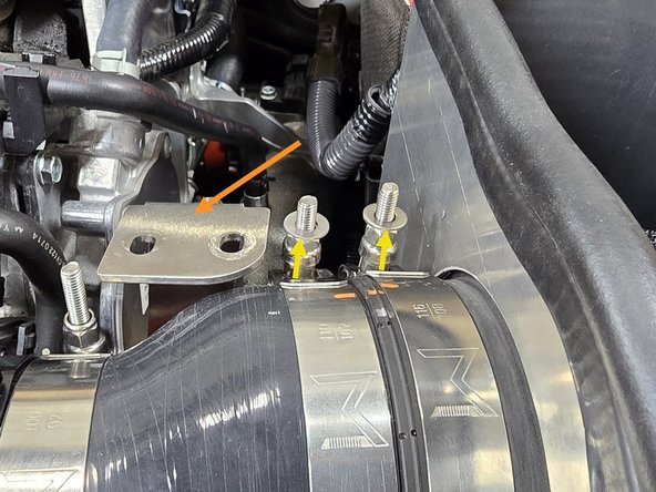
Moving the lower bracket, align the hole on the bracket with the hole in the bottom of the shroud as shown
-
Press the provided 12mm bolt through the shroud and the bottom bracket
-
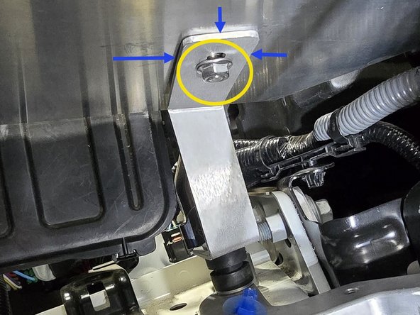
Hand thread the provided M6 flange nut onto the bottom of the bolt as shown
-
The bracket and shroud may not sit completely flush, this is ok tightening the bolt will pull both into the correct position
-
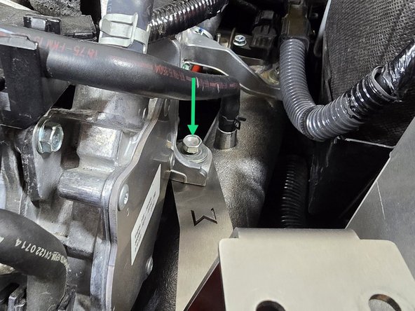
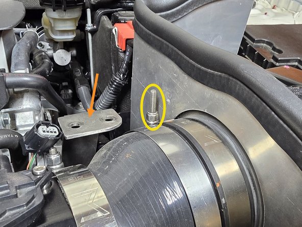
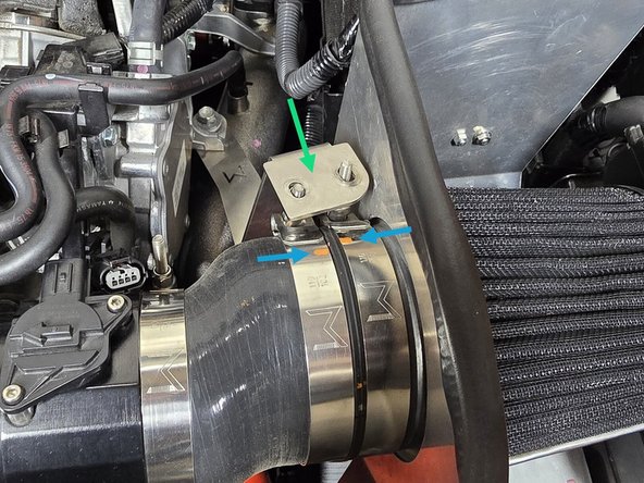
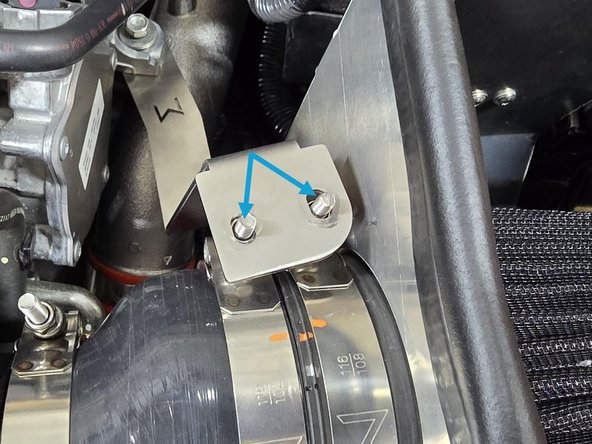
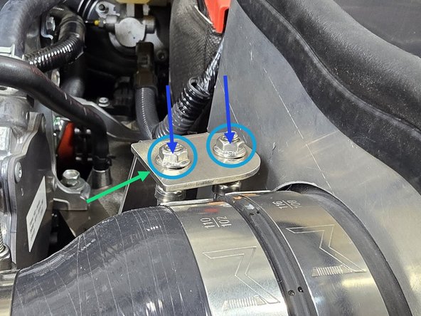
Using a 10mm socket, and a 10mm wrench tighten the flange bolt and flange nut combo circled in green
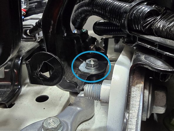
-
Using a 3mm Allen wrench, and a 8mm wrench tighten down the two M5 bolts circled in blue
-
The air filter blocks the use of a longer T-handle Allen bit, so you will need a standard 90 degree bent Allen wrench
-
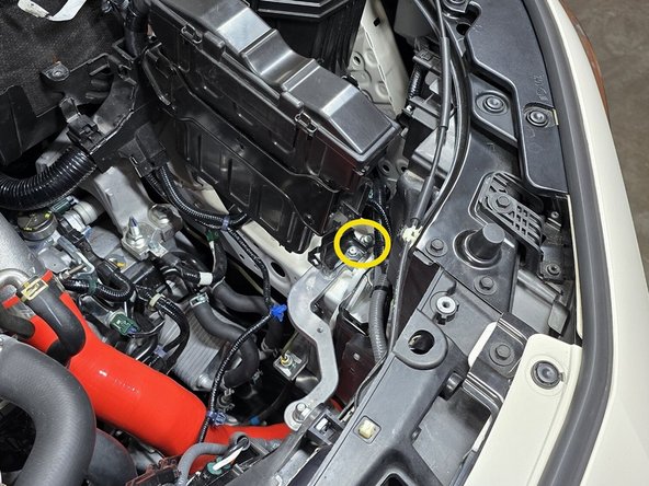
Using a 10mm socket and a long extension tighten down the bolt circled in purple to secure the battery bracket
-
-
-
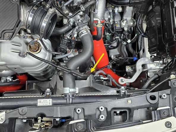
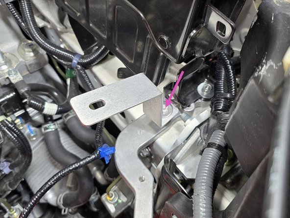
Using a 12mm socket, a long extension, and a 3/8" drive ratchet, remove the bolt securing the cold pipe to the engine bracket
-
While pressing down on the cold pipe, slide the filter bracket in between the cold pipe and the engine bracket
-
Reinstall the previously removed bolt and washer. Leave this bolt loose as you will need to move the bracket around for the next couple of steps
-
-
-
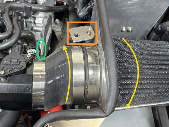
Push the filter bracket off to the side for easy access to the clamps
-
Using a 10mm socket, tighten the 108-116mm clamp until snug
-
Rotate the silicone on the MAF housing until the filer is sitting close to the center of the shroud hole
-
The silicone may sit a little low in the opening of the shroud. This is normal
-
Rotate the air filter until the tightened clamp aligns with the bottom of the bracket as shown
-
-
-
Lift the filter bracket up over the clamp as shown to verify your clamp position
-
With the bracket over the clamp, you will be able to see a very close representation of where the intake will sit once tightened down
-
The clamp position can be changed by rotating the air filter, or the silicone to achieve different positions
-
Once you are happy with the intake position, use a 10mm socket to tighten down the 92-100mm clamp at the MAF housing
-
-
-
With the intake position finalized, move the filter bracket back to the side
-
Using a 10mm socket, tighten the 102-110mm clamp over the silicone until there is enough threads sticking out to verify position, but still loose enough to rotate the clamp
-
Pull the filter bracket over to check the position of the 102-110mm clamp as shown
-
We recommend adding an alignment mark when you first align the two clamps, so that you can easily see how much you've moved the clamp if you need to adjust in the next step
-
You will need to hold the clamp in that same position for the next step!
-
-
-
With the 102-110mm clamp held in the previous position, tighten down until snug, then verify it is even with the 108-116mm clamp
-
As you can see, these clamps are not even! If this is the case, the filter bracket will pull the intake in a weird direction
-
If your clamps are uneven, you will need to repeat this step, and the end of part 3 until they are flush as shown
-
This can be achieved by slightly rotating the 108-116mm clamp, then tightening it until they are flush. This can take a few tries, so be patient
-
Once the clamps are flush, push the bracket over to verify the stud spacing is correct
-
-
-
With the clamp position finalized, push the filter bracket to the side
-
Place the provided M6 washers over the clamp studs as shown
-
Pull the filter bracket back over the studs
-
Thread the provided M6 flange nuts onto the studs above the filter bracket as shown
-
Using a 10mm socket, tighten down the two flange nuts as shown
-
With everything tightened down, if the filter position is not correct, you will need to repeat parts 3 & 4 making small clamp adjustments until it is satisfactory
-
Using a 12mm socket and a long extension, tighten down the cold pipe mounting bolt
-
-
-
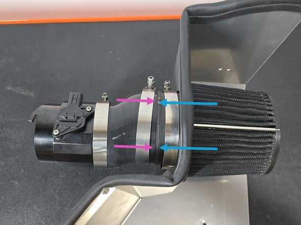
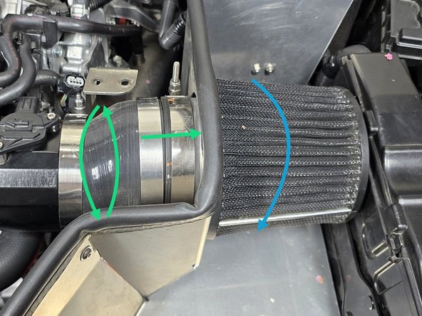
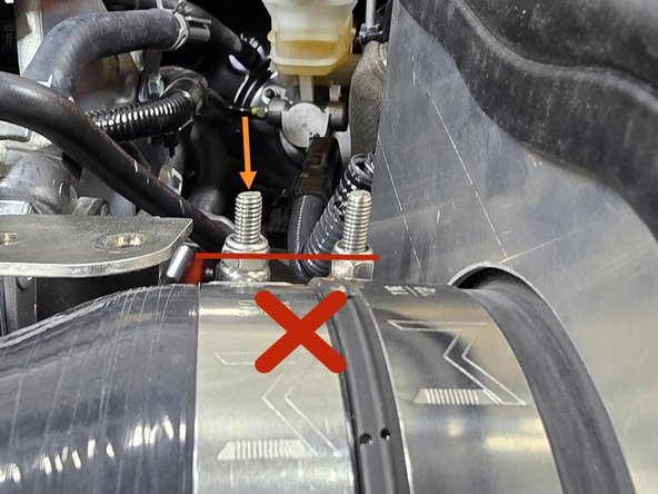
When the filter bracket is tightened down it may rotate the MAF housing as shown
-
If the MAF housing is twisted out of position as shown, loosen the 92-100mm clamp circled in yellow and rotate the MAF housing until it is fully locked in as shown
-
Once the MAF housing is fully locked in, use a 10mm socket to retighten the 92-100mm clamp
-
Verify there is no gap between the MAF housing and the EVAP elbow as shown
-
Route the MAF sensor wire under the MAF housing and press it into the MAF sensor as shown
-
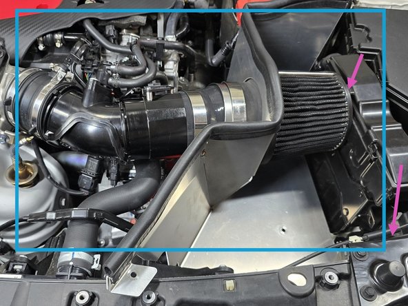
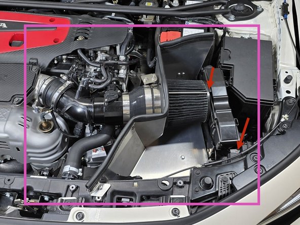
The properly installed intake should appear as shown
-
If the air filter is making contact with the ECU once everything is tightened down, you can tighten the drivers side ECU mounting bolt (Step 10) to compress the included black spacer and pull the ECU away from the intake
-
-
-
This step will only apply to the DE5 Integra, if you are installing our intake on a FL5 Type R you can skip this step and get straight to ripping!
-
Removing the hood insulation is necessary to ensure the intake heat shield has a proper seal to the hood
-
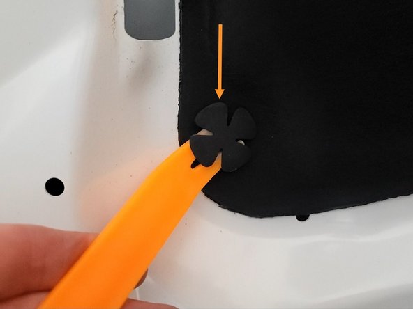
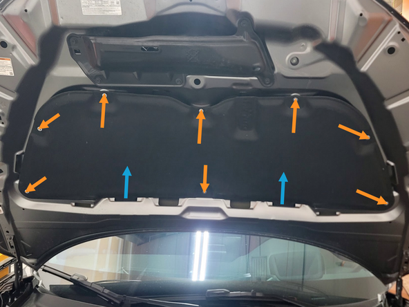
Remove the eight plastic clips that hold hood insulation in place using clip removal tool
-
Lift the insulation up and out of the lower slot on the hood
-
-
-
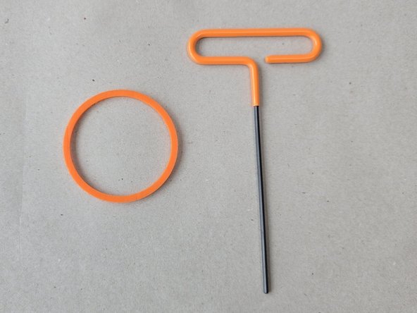
At the end of this install you will be left with our 27WON T-handle Allen wrench and a spare MAF housing O-ring
-
The MAF housing O-ring installed in your MAF housing will wear over time and when the intake is removed and reinstalled multiple times. If it feels like the connection between your MAF housing and your EVAP elbow is getting loose, you can replace the O-ring for a tight, refreshed feel!
-
The Vertical Bulb Trim Seal will wear out over time and can be replaced as desired to keep intake air temperatures as cool as possible
-
The air filter can be serviced many times before replacement. If it shows excessive wear at the shroud interface it can be replaced
-
-
-
This completes the installation of your 27WON Hybrid Cold Air Intake
-
We hope you were impressed with your 27WON experience and love your new intake for years to come. Email us at sales@27won.com or call us at 571-271-0271 with any questions or concerns
-
Please Leave a review here: https://store.27won.com/2023-honda-civic...
-
Share your experience using #27WON on Instagram and Facebook
-
We recommend you check our video on cleaning the air filter at https://youtu.be/nE7diTeI4Gw
-