Introduction
In this installation guide we have provided step by step instructions to remove the OEM boost tubes and install the 27WON Performance Boost Tubes.
Advisory:
- Working under the vehicle requires a safe and sturdy location for the vehicle to sit on jackstands.
- The engine bay will be hot after recent vehicle operation. Allow the vehicle to cool or use a fan to cool the engine bay before working on the vehicle.
Tools
-
-
First and foremost; THANK YOU for becoming a part of the 27WON Family. We hope to REDEFINE your experience of the aftermarket with the highest level Parts, Customer Service, Packaging, & Support
-
The 27WON Boost Tubes are designed with OEM like fitment and closely match overall size and routing. However, fitment with non-27WON aftermarket intakes and intercooler kits is not guaranteed
-
This is shown on an FL5 Type R. The process is identical on the Integra Type S
-
-
-
Raise the vehicle and support with jackstands in the OE recommended locations
-
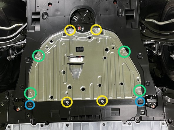
Locate the engine undertray to gain access to the OEM hot side boost tube and lower section of the OEM cold side boost tube
-
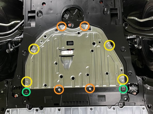
Remove the four Phillips head bolts using a Phillips screwdriver
-
Remove the four quarter turn screws using a large Flathead screwdriver
-
Remove the two Philips head screws using a Philips screwdriver
-
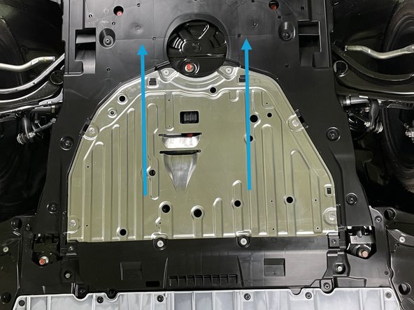
Slide the metal section rearward and remove it from the vehicle
-
The metal section of the undertray can be sharp. Use caution when handling it
-
-
-
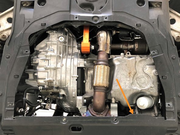
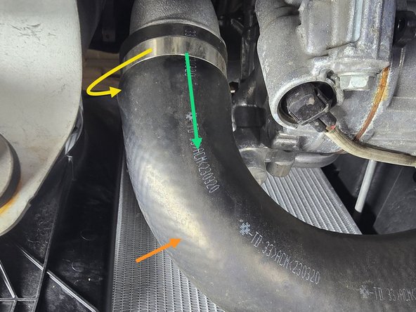
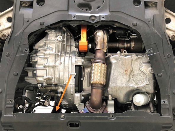
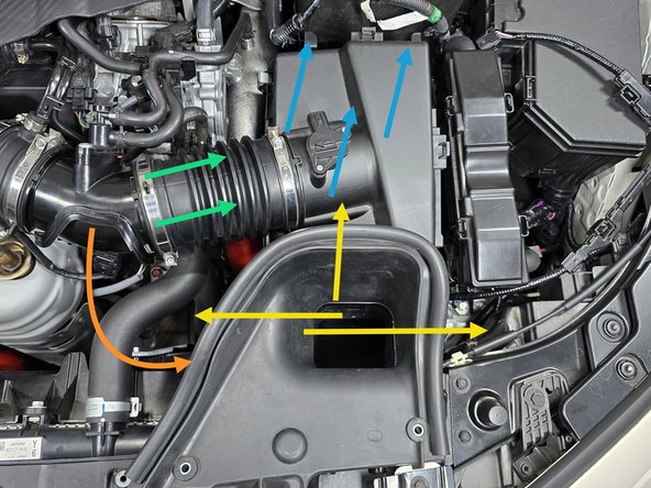
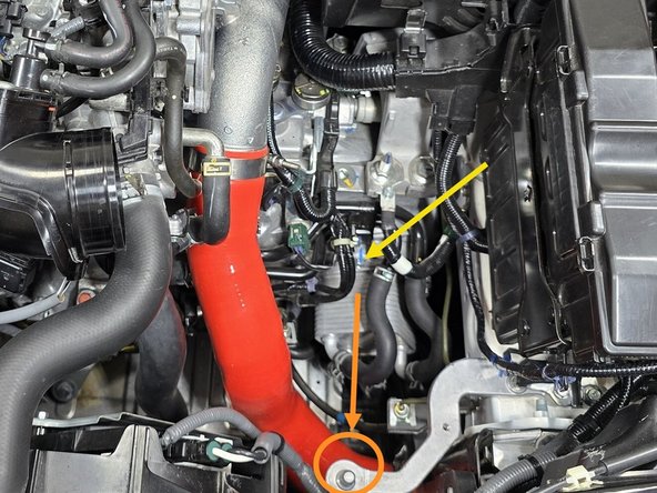
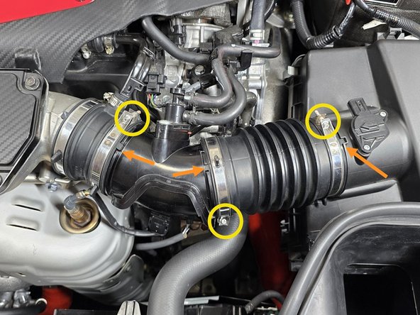
Locate the OEM hot side boost tube. It's in the general area of the orange arrow
-
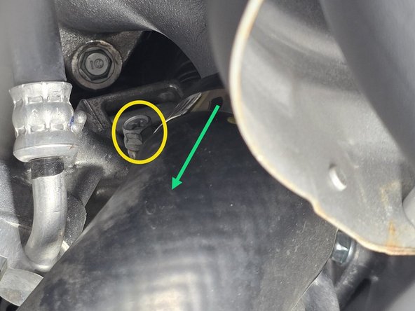
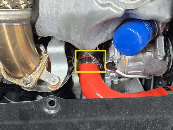
Loosen the clamp that connects the OEM hot side boost tube to the turbocharger using a 10mm socket and a 3/8" drive ratchet
-
Slide the clamp toward the center of the OEM hot side boost tube and out of the way
-
-
-
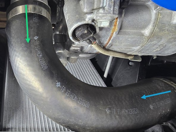
Loosen the clamp that attaches the OEM hot side boost tube to the intercooler using a 10mm socket and ratchet
-
Slide this clamp toward the center of the OEM boost tube and out of the way
-
Pull the OEM boost tube free from the turbocharger
-
Pull the OEM boost tube free from the intercooler and remove it from the vehicle
-
-
-
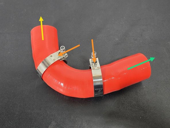
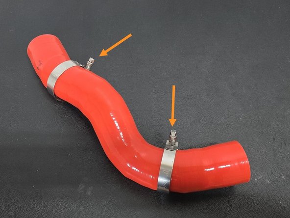
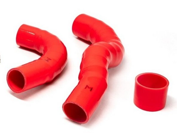
Locate the 27WON hot side boost tube
-
Install the two supplied 60-68mm clamps near the center of the boost tube as shown
-
The boost tube will go into the car in the orientation shown
-
Turbo side
-
FMIC side
-
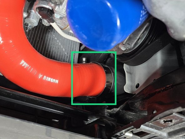
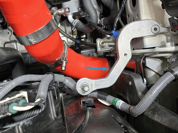
Push the 27WON boost tube onto the turbocharger until flush with the stopper as shown
-
Push the 27WON boost tube onto the intercooler until flush with the stopper as shown
-
-
-
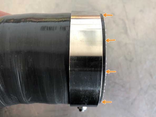
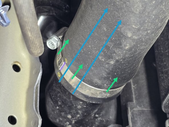
Image 1 on this page shows what we mean by "correctly positioning" the clamps. There should be a small gap between the clamp and the end of the silicone (2-4mm). This gap should be even all the way around the silicone. Use this image as a reference when tightening all supplied clamps
-
Correctly position the 60-68mm clamp on the turbocharger and tighten with a 10mm socket and 3/8" drive ratchet until the silicone starts to bulge slightly at the edge of the clamp
-
The clamp orientations shown are the easiest to access/tighten
-
Correctly position the 60-68mm clamp on the intercooler as shown and leave to be tightened from above later
-
This clamp can be tightened now, but is much easier to reach from above with a 12" extension
-
-
-
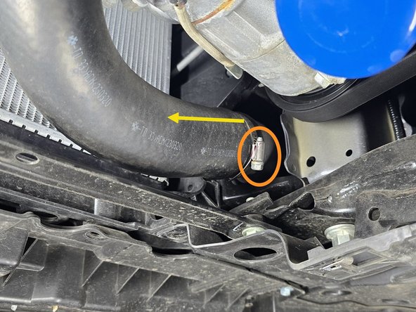
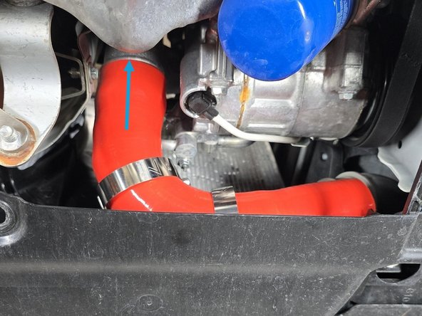
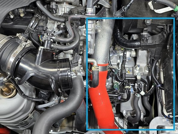
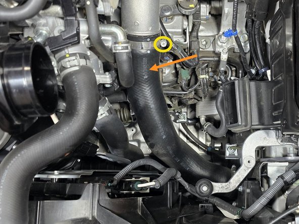
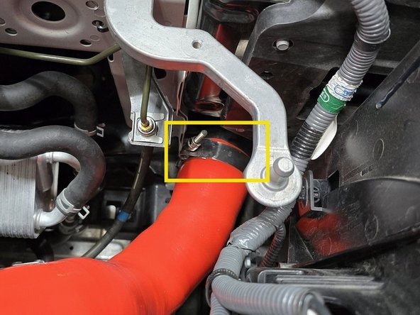
Locate the lower portion of the OEM cold side boost tube. It's in the general area of the orange arrow
-
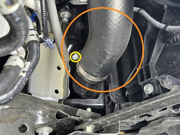
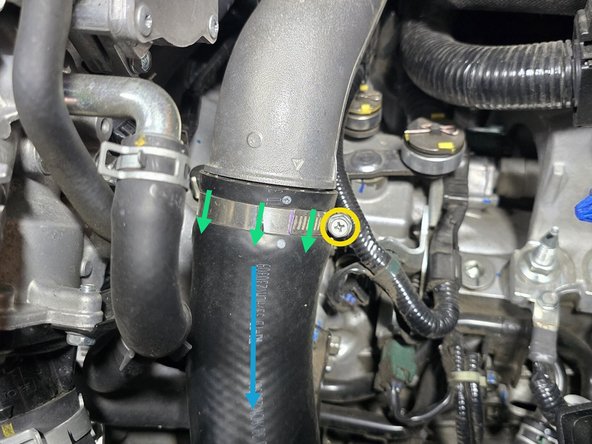
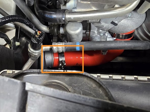
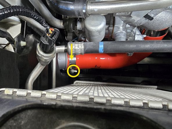
Loosen the clamp that connects the OEM cold side boost tube to the intercooler using a 10mm socket and 3/8" drive ratchet
-
Slide the clamp up the tube and out of the way
-
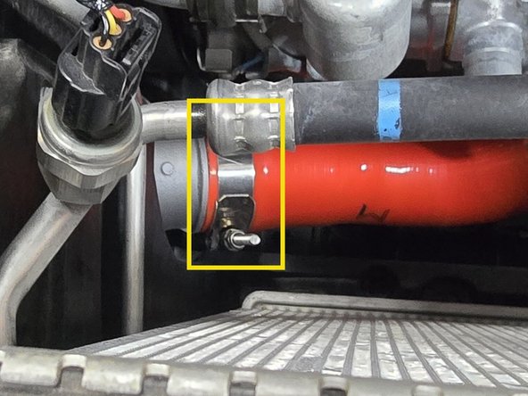
Pull the OEM boost tube free from the intercooler
-
-
-
OE Intake removal is shown next. Skip to Step 14 and follow manufacturers instructions for aftermarket intakes
-
Moving back to the topside of the engine, begin removing the intake to gain access to the OEM cold side boost tube
-
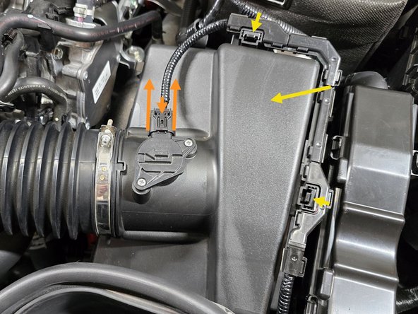
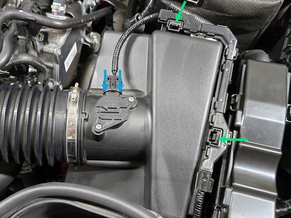
Unplug the connector for MAF sensor by using your fingers to press down on the plastic clip and pulling the plug away from the airbox as shown
-
Using your finger press the two tabs shown towards the airbox, and lift on the wire loom to disconnect the loom from the airbox lid
-
Set the MAF sensor wire out of the way
-
-
-
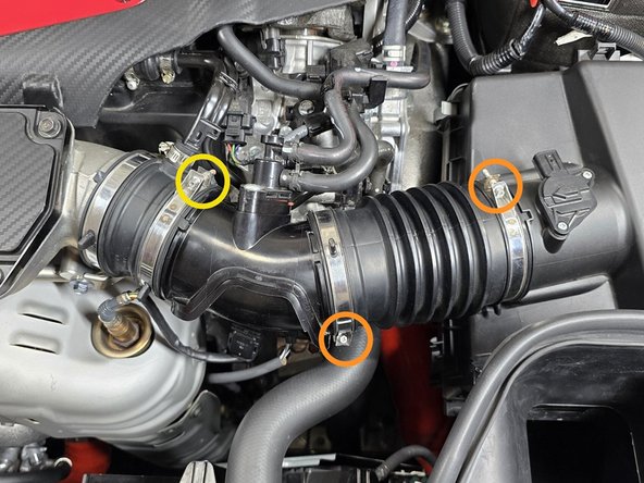
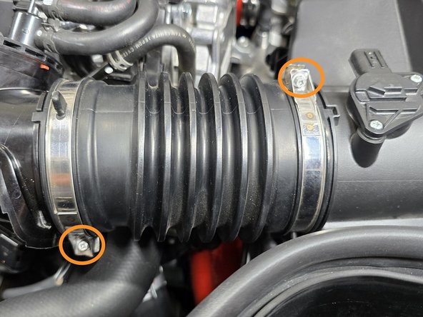
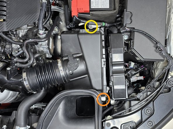
Use a 5.5mm socket and 3/8" ratchet or a small Phillips screwdriver to loosen the two intake clamps circled in orange
-
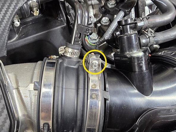
Use a 5.5mm socket and 3/8" ratchet or a small Phillips screwdriver to loosen the one EVAP elbow clamp circled in yellow
-
-
-
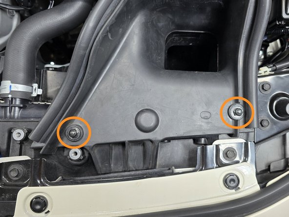
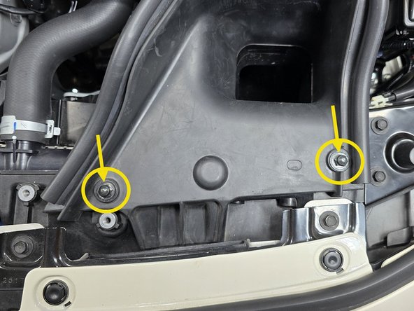
Use a 3/8" drive ratchet and a 10mm socket to remove two (2) bolts that hold the intake duct in place
-
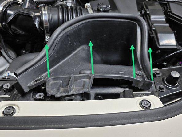
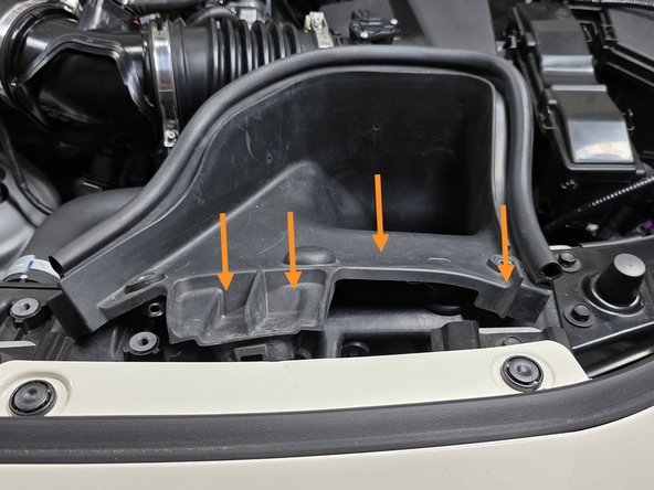
Using your hand pull the rubber end of the duct out of its slot in the radiator shroud
-
This may take a bit of force the first time it comes out
-
-
-
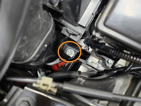
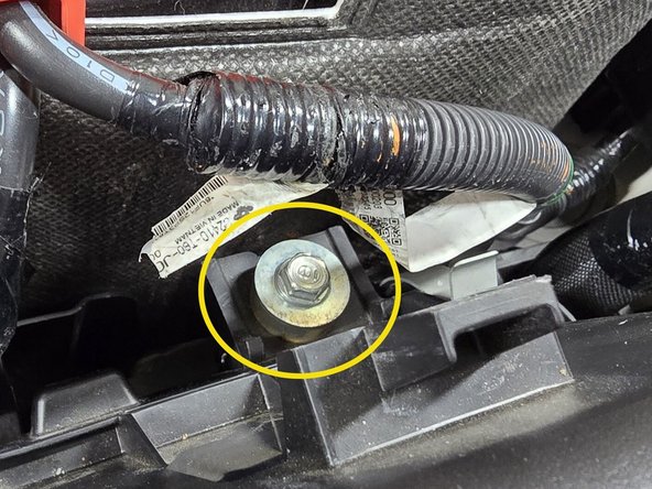
Use a 3/8" ratchet, a long extension, and a 10mm socket to remove lower intake bolt
-
Use a 3/8" ratchet, a long extension, and a 10mm socket to remove the upper battery bracket bolt
-
-
-
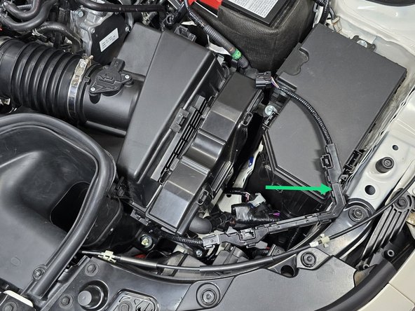
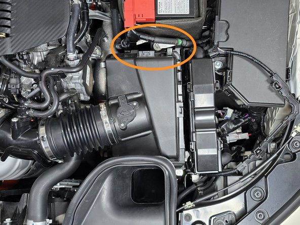
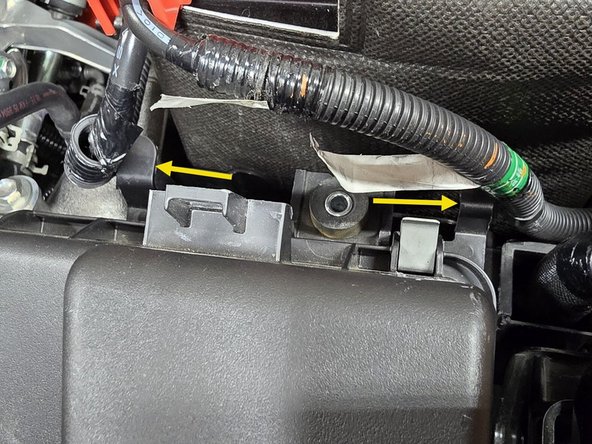
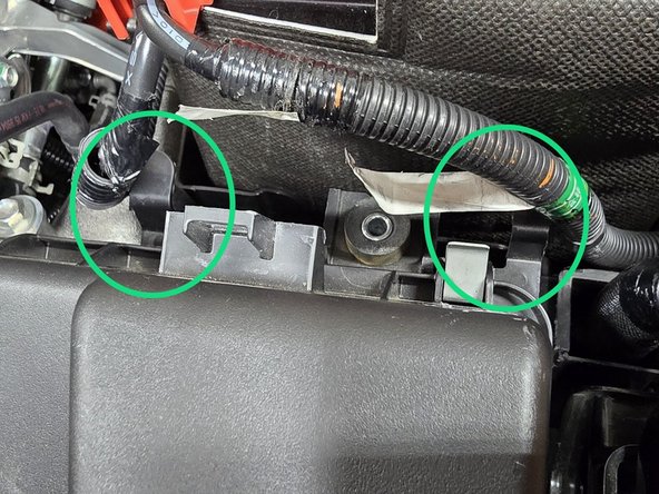
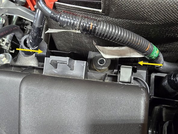
Locate the two positive battery cables that need to be freed from the upper airbox in order to remove the airbox
-
Using your fingers or a pair of needle nose pliers pinch the two battery cable clips and push them out of the airbox bracket
-
Only one side is shown, the other side is the same process
-
-
-
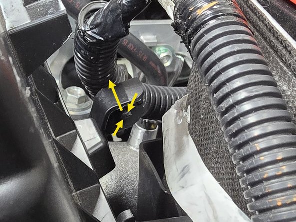
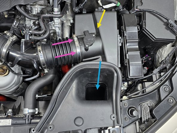
The airbox is still connected to the chassis with a rubber grommet and stud underneath the intake inlet in the area shown
-
Wiggle the inlet back and forth while lifting on the entire airbox to get it loose from the grommet as shown
-
Using your hand pull the accordion intake tube off of the hard plastic EVAP elbow as shown
-
With the intake tube now freed, pull the airbox assembly out of the engine bay
-
-
-
Locate the cold side boost tube
-
Using a 10mm socket and 3/8" drive ratchet, loosen the clamp where the OEM boost tube connects to the OEM cold pipe
-
Slide this clamp down the OEM boost tube
-
Pull the OEM boost tube free from the OEM cold pipe
-
Remove the OEM cold side boost tube from the engine bay
-
-
-
Locate the 27WON cold side boost tube
-
Install the two supplied 63-71mm clamps away from the ends of the silicone as shown
-
Position the boost tube in the orientation shown
-
Cold pipe end
-
Intercooler end
-
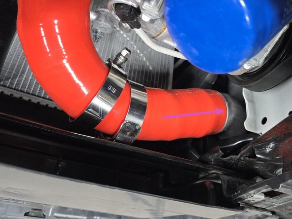
Push the 27WON boost tube onto the intercooler until flush with the stopper as shown
-
Push the 27WON boost tube onto the cold pipe until flush with the stopper as shown
-
-
-
Correctly position the 63-71mm clamp over the cold pipe and tighten with a 10mm socket and 3/8" drive ratchet until the silicone starts to bulge slightly at the edge of the clamp
-
Correctly position the 63-71mm clamp over the Intercooler and tighten with a 10mm socket, a 12" extension, and a 3/8" drive ratchet until the silicone starts to bulge slightly at the edge of the clamp
-
See Step 6 for correct clamp positioning
-
The clamp orientations shown are easy to access and provide clearance to airboxes and intakes
-
-
-
If you tightened this clamp while under the car, you can skip this step
-
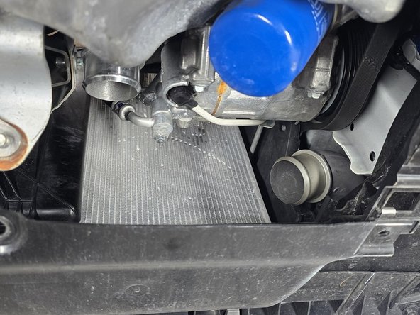
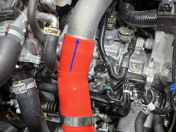
Looking down between the radiator and turbocharger you can get a straight shot at the connection between the hot side boost tube and intercooler
-
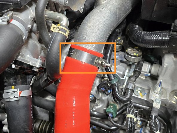
Correctly position the 60-68mm clamp on the intercooler and tighten with a 10mm socket, a 12" extension, and 3/8" drive ratchet until the silicone starts to bulge slightly at the edge of the clamp
-
If the 12" extension does not provide enough clearance, a longer extension or a stack of multiple extensions can provide better reach
-
-
-
The battery, and battery tray will need to be removed for easy access to the throttle body silicone
-
If you have an FSTB installed it will need to be removed before proceeding
-
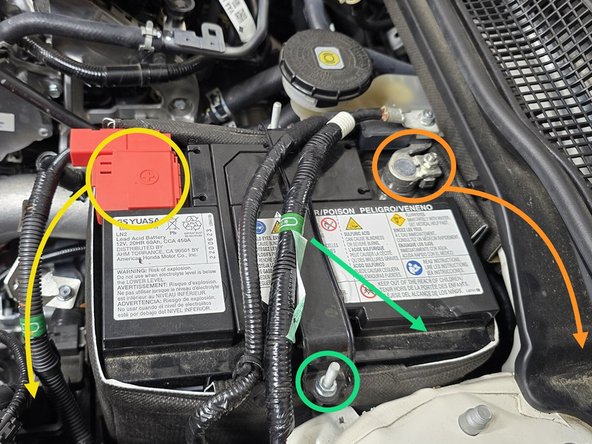
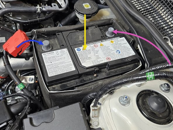
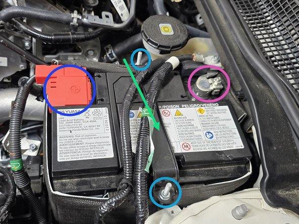
Loosen the nut on the negative battery cable with a 10mm socket and a 3/8" drive ratchet then remove the negative cable from the battery. Tuck the cable out of the way
-
Loosen the nut on the positive battery cable with a 10mm socket and a 3/8" drive ratchet then remove the positive cable from the battery. Tuck the cable out of the way
-
Loosen one of the nuts on the battery tiedown with a 10mm socket and a 3/8" drive ratchet then remove the hook and battery tiedown from the battery
-
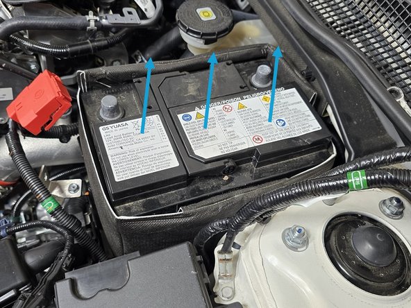
With the cables and tiedown out of the way lift the battery out of the engine bay and set it to the side
-
Note that there may be a handle on your battery that makes removal easier
-
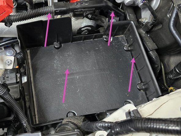
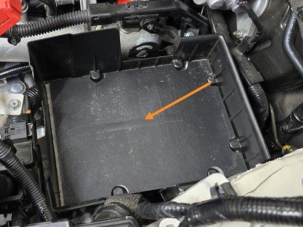
Remove the plastic battery tray from the engine bay to expose the lower metal battery tray
-
-
-
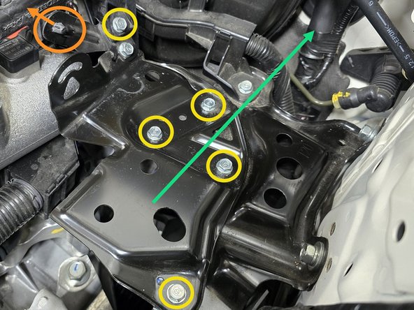
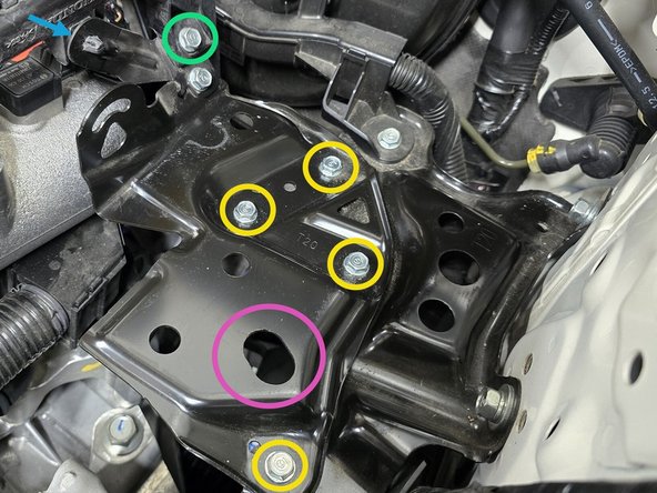
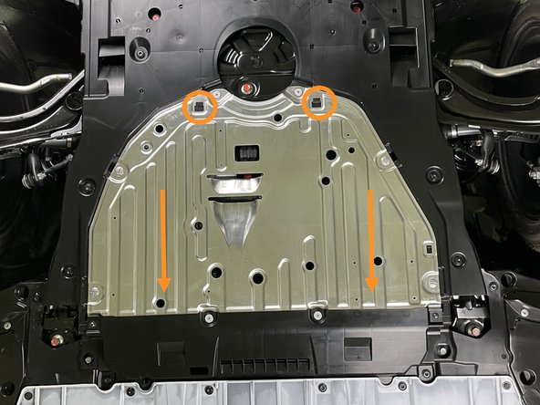
Use your fingers or a pair of pliers to pinch the clip circled in orange and push it out of the bracket
-
Use a 10mm socket, a 6" extension, and a 3/8" drive ratchet to remove the five bolts circled in yellow
-
With the lower battery tray free, remove it from the engine bay as shown
-
-
-
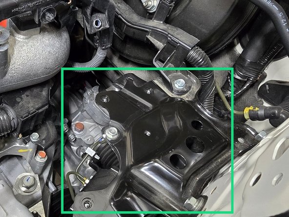
The cold pipe will need to be unbolted from the engine block brackets to allow the necessary movement to remove the throttle body silicone
-
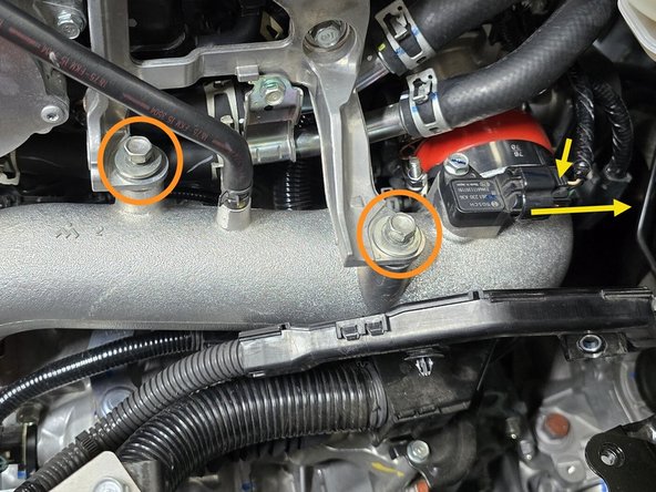
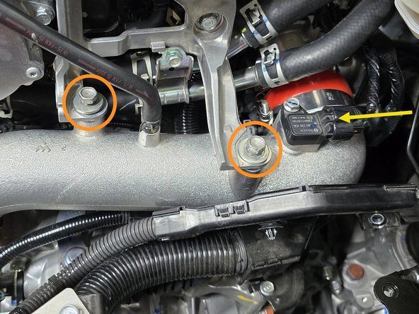
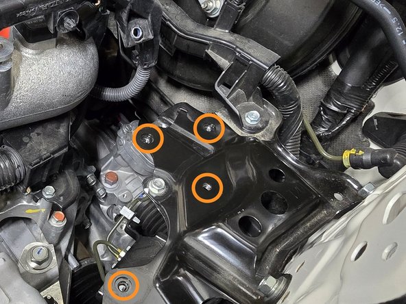
Use a 12mm socket, a 6" extension, and a 3/8" drive ratchet to remove the two mounting bolts circled in orange
-
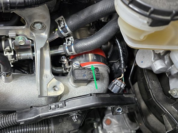
Unplug the MAP sensor by pressing down on the mounting tab, and pulling the plug towards the firewall
-
-
-
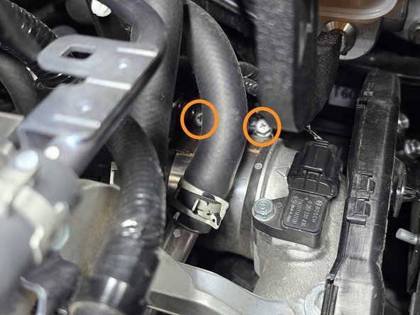
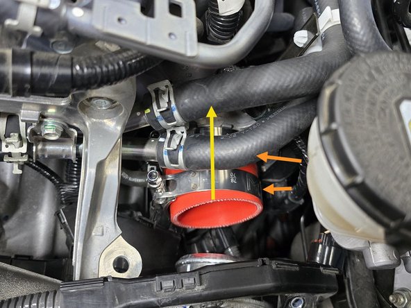
Use a 10mm socket, a 6" extension, and a 3/8" drive ratchet loosen the two hose clamps securing the OEM silicone
-
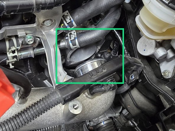
With both clamps loose, pull the cold pipe towards the drivers side of the vehicle and out of the throttle body silicone
-
With the cold pipe out of the way, remove the OEM silicone as shown
-
-
-
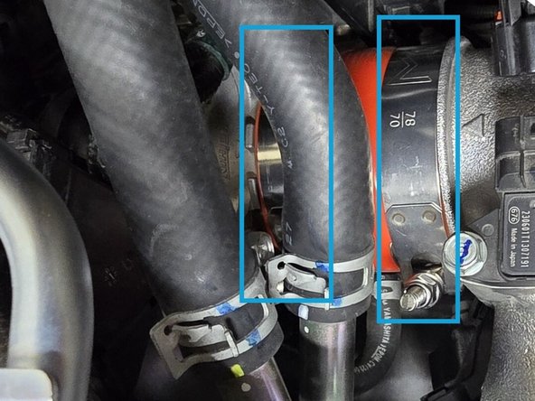
Loosely place the 70-78mm clamps on the 27WON silicone
-
This silicone is not directional, so the orientation of the silicone itself is not important
-
While holding the cold pipe out of the way, push the silicone over the throttle body until flush with the stopper on the throttle body
-
Push the cold pipe into the silicone until flush with the stopper on the cold pipe as shown
-
Correctly position the 70-78mm clamps on the throttle body and cold pipe, and tighten with a 10mm socket, a 6" extension, and 3/8" drive ratchet until the silicone starts to bulge slightly at the edge of the clamp
-
-
-
Thread the two mounting bolts into the cold pipe as shown then use a 12mm socket, a 6" extension, and a 3/8" drive ratchet to tighten them down
-
Plug the MAP sensor back in as shown
-
-
-
The lower battery bracket will need to align with the four holes circled in orange when reinstalled
-
Thread the four mounting bolts as shown, then use a 10mm socket, a 6" extension, and a 3/8" drive ratchet to tighten them down
-
Thread the wire mounting bolt through the plastic loom as shown, then use a 10mm socket, a 6" extension, and a 3/8" drive ratchet to tighten the bolt down
-
Press the wire mounting clip through the bracket as shown until it "clicks" into place
-
The plastic battery tray will slot into the hole circled in pink
-
-
-
Place the plastic battery tray into the engine bay in the orientation shown, the plastic alignment pin on the bottom will slot into the hole circled in the last step
-
Place the battery into the plastic tray in the orientation shown
-
Place the battery tie down over the battery in the orientation shown, with the shorter hook towards the drivers side of the vehicle
-
Place the tie down hooks into their respective holes, then tighten down the two nuts with a 10mm socket, and a 3/8" drive ratchet until snug
-
If these are too tight the tie down can damage the battery cap
-
Place the positive cable over the positive terminal, then use a 10mm socket, and a 3/8" drive ratchet to tighten the terminal clamp
-
Place the negative cable over the negative terminal, then use a 10mm socket, and a 3/8" drive ratchet to tighten the terminal clamp
-
-
-
OE Intake installation is shown next. Skip to Step 31 and follow manufacturers instructions for aftermarket intakes
-
When reinstalling the airbox there is a rubber grommet on the bottom of the box that must fit on an aluminum peg in the engine bay
-
Insert the airbox into the engine bay in a similar manner that it was removed
-
The front will sit in an approximately correct location while the back pivots downward
-
Use care when maneuvering the rear brackets around the battery cables so as to not damage the cables
-
Press the front of the airbox down over the aluminum peg mentioned above
-
You should be able to feel the peg insert into the rubber grommet
-
Press the OEM intake tub over the airbox lid as shown
-
-
-
The battery cables will need to be reconnected to the airbox in the location shown
-
Press the plastic clips on the battery cables into the mounting holes on the airbox as shown
-
-
-
The airbox may need to be shifted around to align the mounting bolts with their matching threaded holes
-
Using a 10mm socket, and a 12" extension hand thread the lower mounting bolt
-
Use the same combination of tools and a 3/8" drive ratchet to tighten down the lower airbox mounting bolt
-
Using a 10mm socket, and a 12" extension hand thread the upper battery bracket bolt
-
Use the same combination of tools and a 3/8" drive ratchet to tighten down the upper battery bracket bolt
-
-
-
Use your hand to press the intake inlet back into its slots on the radiator shroud
-
This will require a bit of force, and some moving back and forth to ensure it is fully seated the first time
-
Hand thread the two inlet mounting bolts in the locations shown
-
Use a 10mm socket and a 3/8" drive ratchet to tighten both bolts
-
-
-
Verify the OE intake tube and EVAP elbow are fully seated in the locations shown
-
Use a 5.5mm socket and 3/8" ratchet or a small Phillips screwdriver to tighten the three intake clamps circled in yellow
-
Press the MAF wire loom into the mounting tabs on the airbox lid as shown
-
Plug the MAF sensor back in
-
-
-
The final bit of this install will be done under the vehicle
-
Lift the metal section of the undertray into position
-
The front edge of the metal will fit over the top of the rear edge of the plastic section of the undertray
-
To secure, push the skidtray forwards onto the two tabs that will hold it in position
-
Reinstall the four Phillips head screws and tighten until tight using a Phillips screwdriver
-
Reinstall the four quarter-turn screws and tighten using a large Flathead screwdriver. This will "click" into position when tight
-
Reinstall the two Philips head screw and tighten using a Philips screwdriver
-
-
-
This completes the installation of your 27WON Performance Boost Tubes
-
We hope you were impressed with your 27WON experience and love your new Boost Tubes for years to come. Email us at sales@27won.com or call us at 571-271-0271 with any questions or concerns
-
Please Leave a review here: https://store.27won.com/honda-civic-type...
-
Stay Connected with the latest developments with the 27WON Monthly Newsletter: https://store.27won.com/27won-newsletter...
-
See the latest Products and Tech Videos from 27WON with a quick Subscribe: https://www.youtube.com/channel/UCF7uI0N...
-
Share your experience using #27WON on Instagram and Facebook
-