Introduction
In this installation guide we have provided step by step instructions to install the 27WON Performance Kuro Turbo for Civic Type R
Advisory:
- The engine bay will be hot after recent vehicle operation. Allow the vehicle to cool or use a fan to cool the engine bay before working on the vehicle.
Tools
- 3/8" Ratchet
- 1/4" Ratchet
- 3/8" Torque Wrench
- 12mm Wrench
- 14mm Wrench
- 5.5mm Socket
- 10mm Socket
- 10mm Socket - Deep
- 12mm Socket
- 14mm Socket
- 22mm Oxygen Sensor Socket
- 3mm Allen Key Socket
- 5mm Allen Key Socket
- 3/8" 3 in Extension
- 1/4" Ratchet Extension
- Needle Nose Pliers
- Pliers - Small
- Hydraulic Jack
- Jack Stand × 2
- Flathead Screwdriver
- Vice Grips Small-Will be used to pinch coolant Hoses × 2
- 1 Gallon-Honda Genuine Coolant- Required for Coolant System Refill
- WD-40 or other penetrating fluid
- Silicone Lubricant Spray
- Shop Towels/Rags
-
-
First and foremost; THANK YOU for becoming a part of the 27WON Family. We hope to REDEFINE your experience of the aftermarket with the highest level Parts, Customer Service, Packaging, & Support
-
These instructions were written with a 2018 Honda Civic Type R. FL5 and DE5 install process similar
-
These instructions are for both Kuro and Kuro+ turbocharger installation
-
-
-
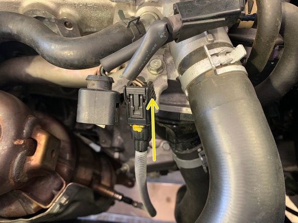
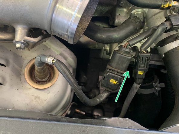
Unplug the MAF sensor by pushing down on the tab (red circle) on top of the wiring connector
-
-
-
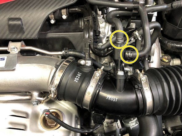
Use needle nose pliers to loosen both OEM spring clamps and slide them up the hoses
-
Pull the Boost Feed and EVAP Dump hoses off the EVAP solenoid
-
-
-
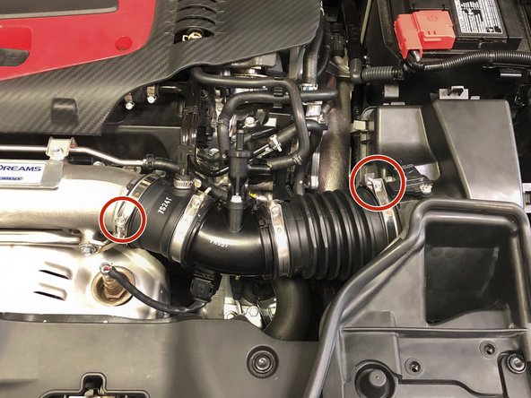
Using the 5.5mm socket and ratchet, loosen the two OEM clamps securing the intake tube
-
Remove the valve cover breather pipe from the intake tube
-
This breather pipe is secured with a permanent OEM clamp. This clamp cannot be removed easily so the pipe will need to be pulled free without removing the clamp. This can be difficult the first time. This permanent clamp will be replaced with the provided regular hose clamp during re-installation
-
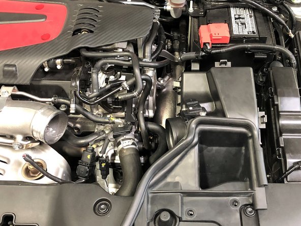
Remove the OEM intake tube from the vehicle
-
-
-
Undo upper oxygen sensor electrical pigtail and let loose out of the way
-
-
-
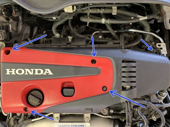
Use a 10mm socket to remove the 5 bolts holding the engine cover
-
Remove the engine cover
-
-
-
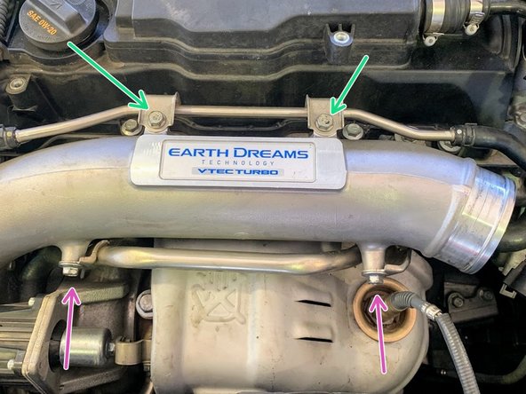
Remove (2) 10mm bolts securing the hard water line to the inlet pipe and move out of the way
-
Remove (2) 10mm bolts securing lower hard water pipe
-
-
-
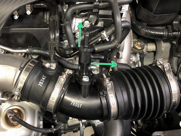
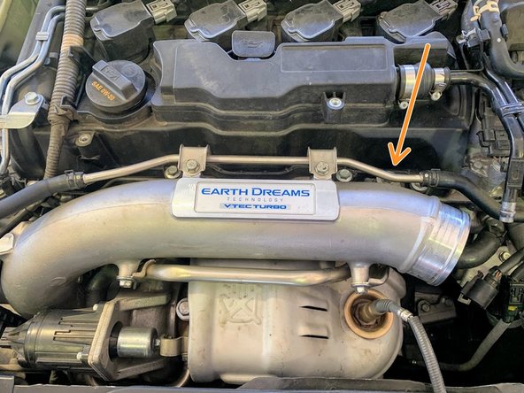
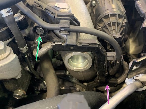
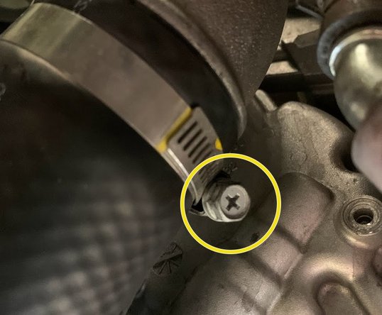
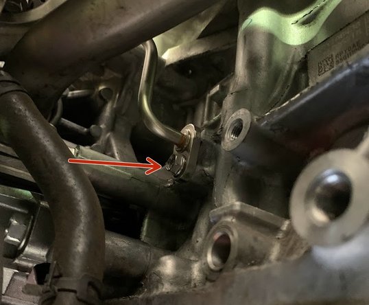
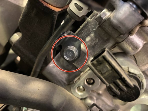
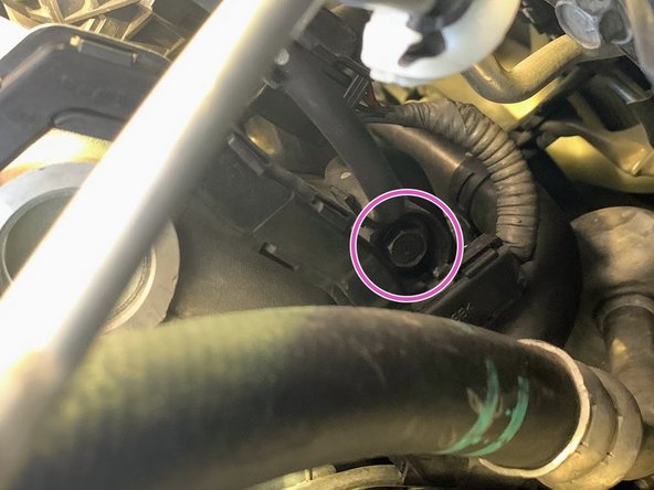
Undo 10 mm bolt on the inlet pipe as shown
-
-
-
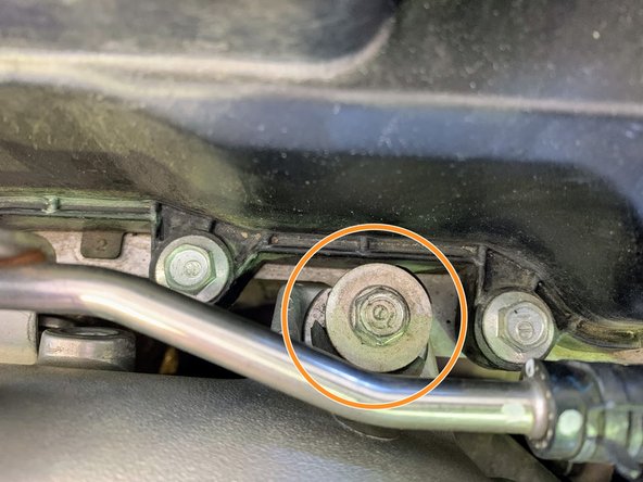
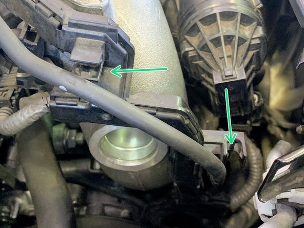
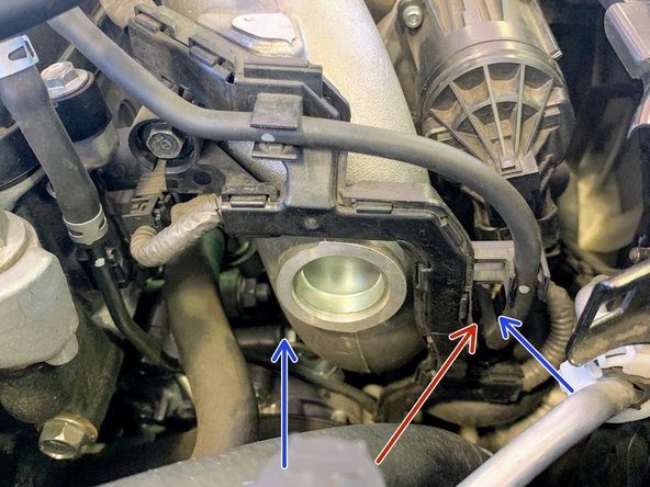
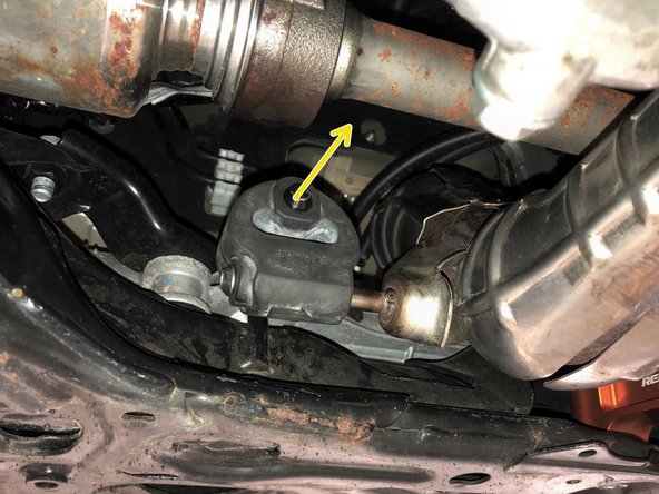
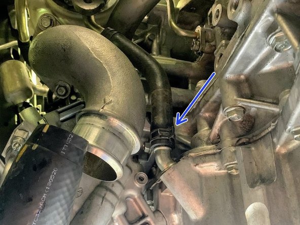
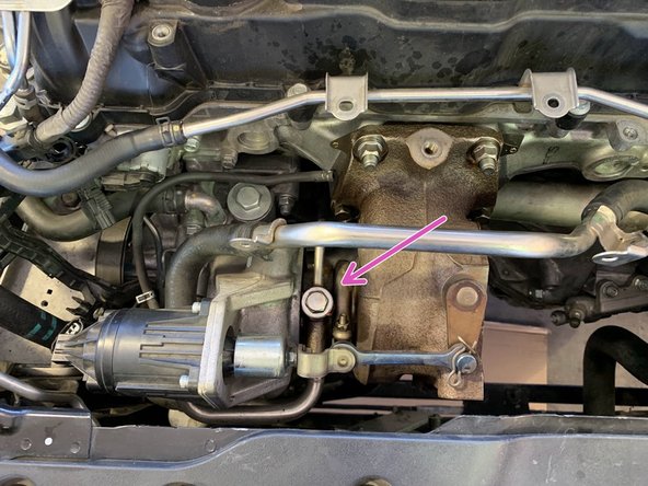
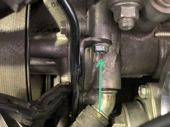
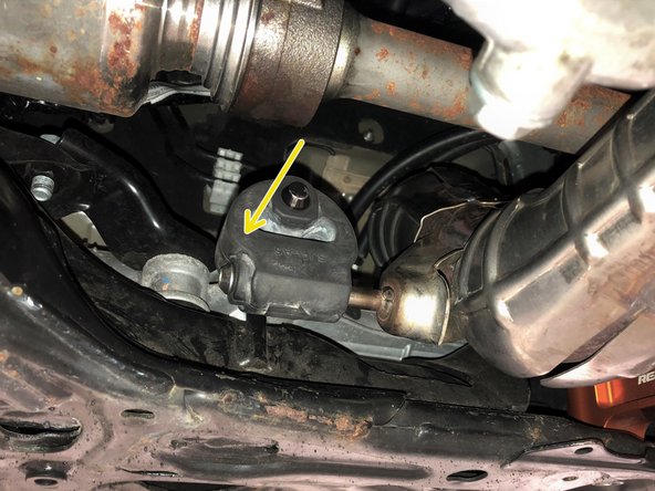
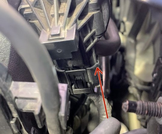
There are 2 bolts holding this bracket. The lower one is well hidden (purple arrow)
-
Using ¼ inch ratchet, 10mm deep socket, and 3 inch extension, remove the 10mm bolt shown
-
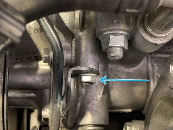
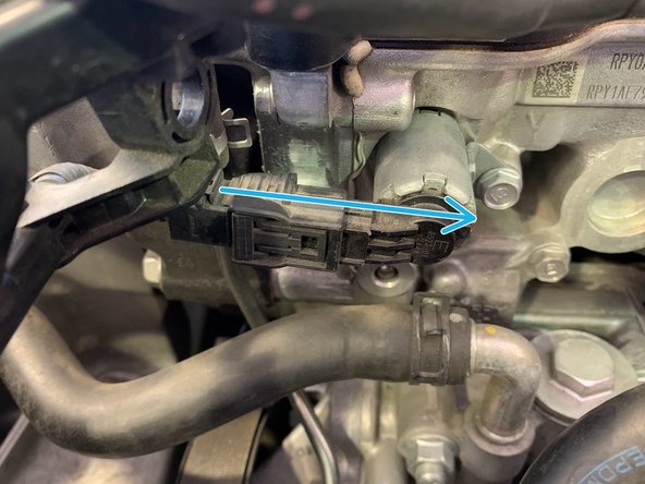
Remove the lower 10mm bolt as shown
-
-
-
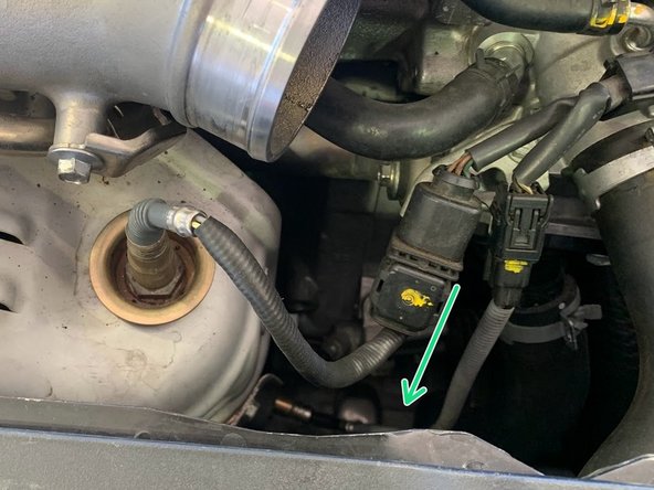
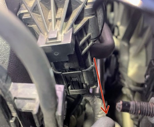
Unplug electrical pigtail of electronic wastegate
-
-
-
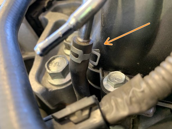
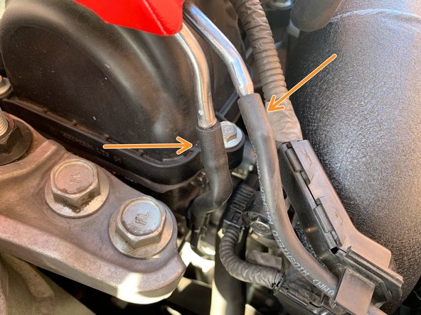
Unclip the vacuum hose from the clips on the vacuum line retainer bracket
-
-
-
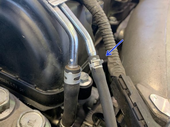
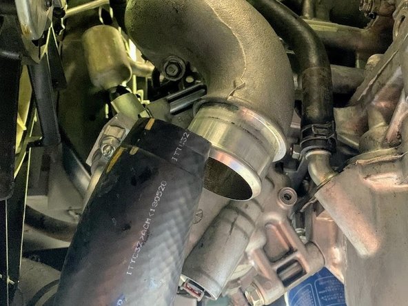
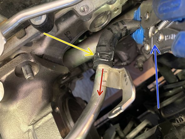
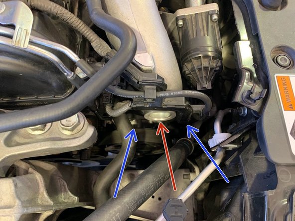
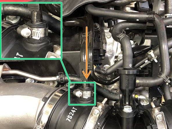
Using needle nose pliers, undo the clamp as shown and free the silicone hose from the hardline
-
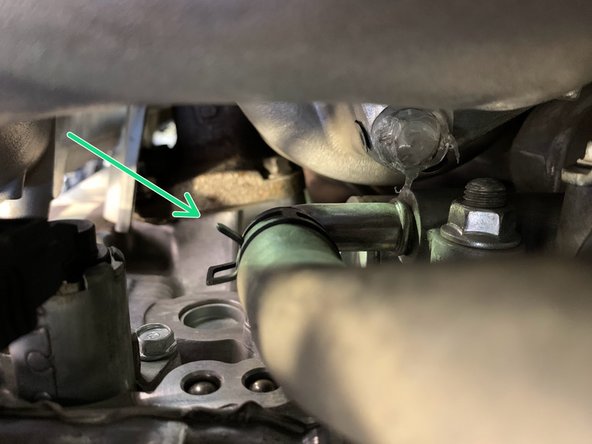
Follow the line down and find the lower clamp holding the hose
-
Undo the lower clamp and free the silicone hose from the receiver
-
Remove the silicone hose from the car and set aside
-
-
-
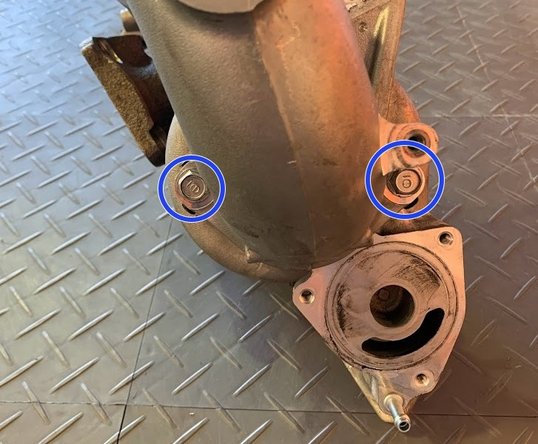
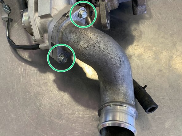
Turbo inlet pipe assembly is shown off the car here because the bolts are hard to see installed on vehicle
-
The (2) 10mm bolts are shown off the car to better demonstrate their location
-
Remove the Inlet Pipe by removing the (2) 10mm bolts shown above, a deep 10mm socket and ~3" extension work best here. These bolts will be reused
-
-
-
Using a 22mm socket remove the upper oxygen sensor
-
Set the sensor out of the way
-
-
-
Jack up your car and secure it with jack stands as you will need to get underneath
-
-
-
Locate the engine undertray to gain access to the exhaust front-pipe
-
Take pictures or take a good look at how the under tray fits with the other under body shields to help with easier reinstallation
-
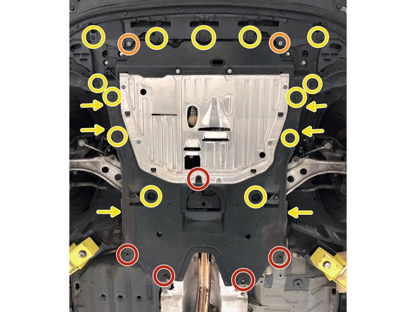
Use a 10mm socket & ratchet to remove the five 10mm bolts (red circles)
-
Use a 5mm Allen Key/Allen Socket to remove the two (2) Allen head bolts (orange circles)
-
Use a Flathead screwdriver or push clip removal tool to remove the 19 push clips from the under tray (yellow circles and arrows)
-
For clarity on the push clips on the sides of the under tray (labeled with the arrows) please proceed to the next step
-
-
-
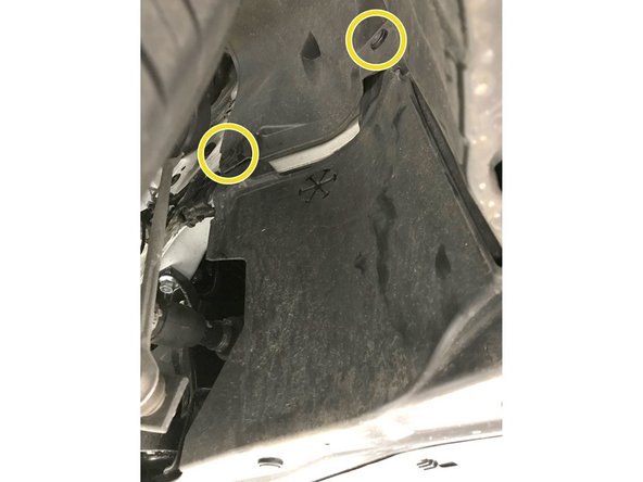
The images in this step show the push clips on the side of the under tray. These are labeled with the arrows in the previous step
-
Passenger side shown, please repeat for the driver side before removing the under tray
-
Remove the engine under tray from the vehicle
-
-
-
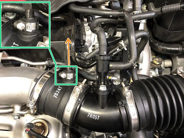
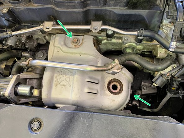
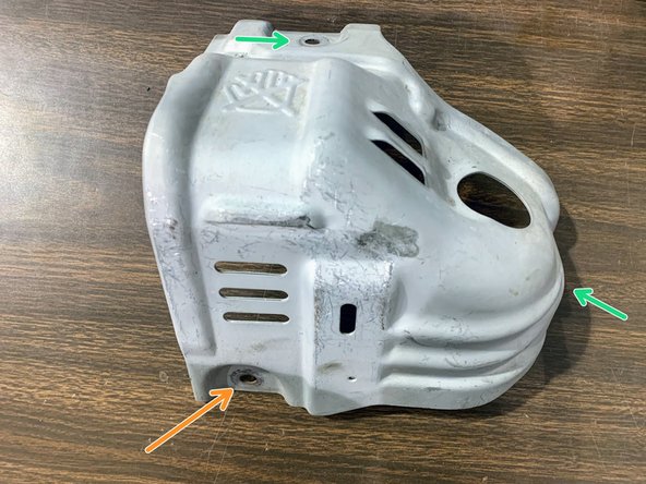
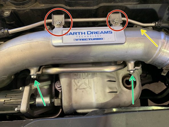
Using a 12mm socket and ratchet, remove the (2) 12mm bolts from the upper part of the heat shield
-
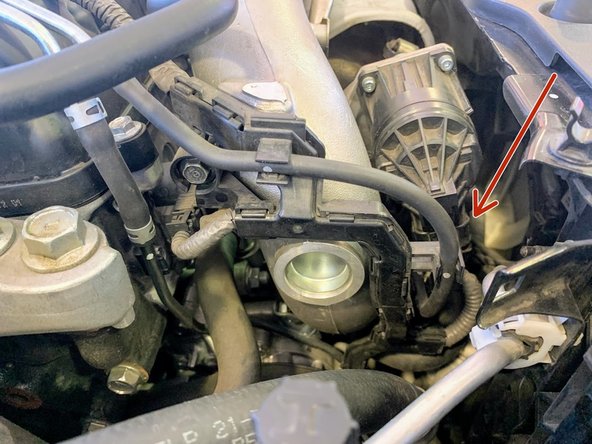
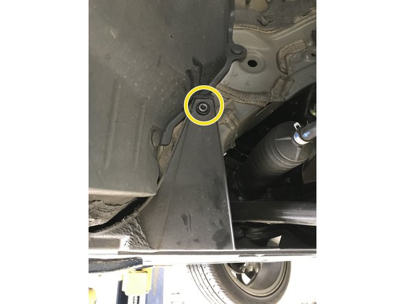
It is very difficult to remove the lower bolt from the heat shield from the engine bay (shown off the car, orange arrow). We advise to remove this bolt from underneath the car
-
Using a 12mm wrench, remove the lower 12mm bolt from the heat shield
-
-
-
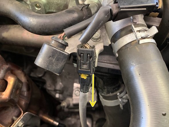
Unplug the lower oxygen sensor electrical pigtail connector located next to the upper oxygen sensor connector
-
-
-
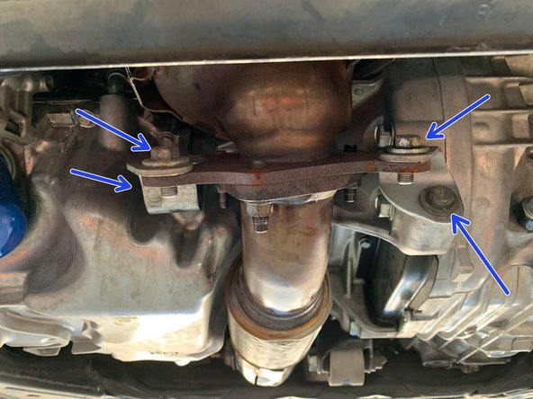
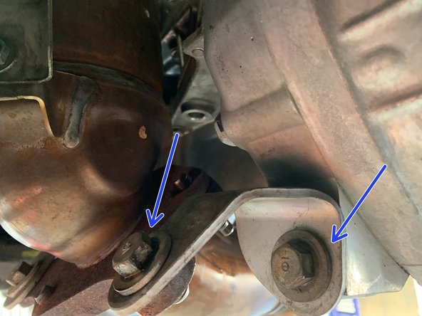
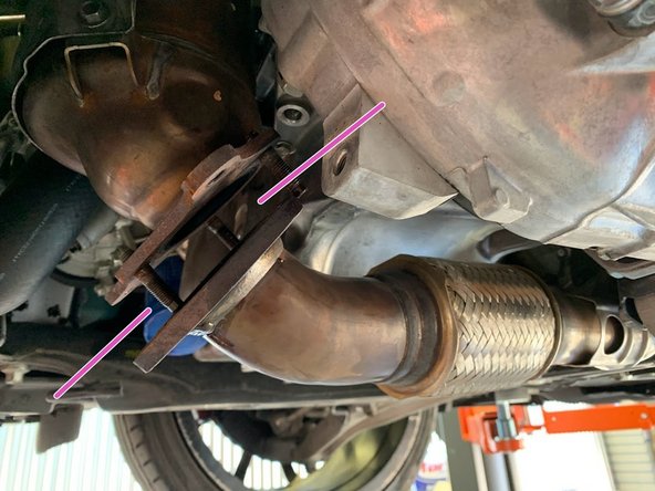
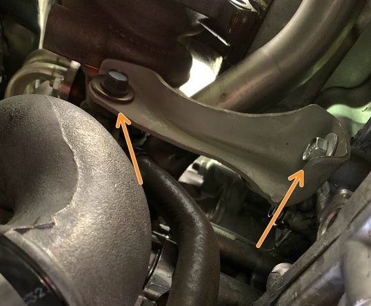
Using a 14mm socket and a 14mm wrench , undo the (4) bolts for the downpipe brackets as shown
-
Remove both of the brackets and set them aside
-
-
-
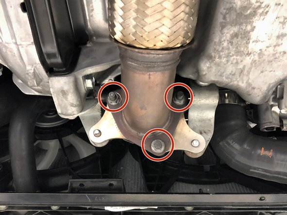
Use a 14mm socket and ratchet to remove the three nuts that connect the front-pipe to the downpipe
-
Pull the rubber hanger on the OE front-pipe free from the hanger rod on the chassis in the direction shown
-
Usually the studs will remain in the downpipe causing issues when removing the downpipe. Pry the downpipe from front pipe by sticking a screwdriver in between the downpipe and the forward pipe
-
-
-
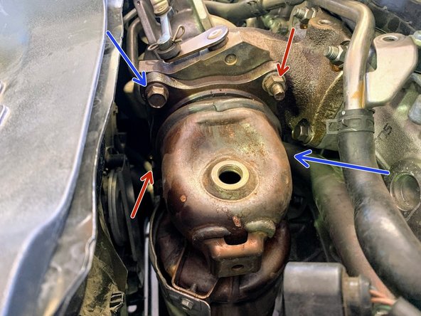
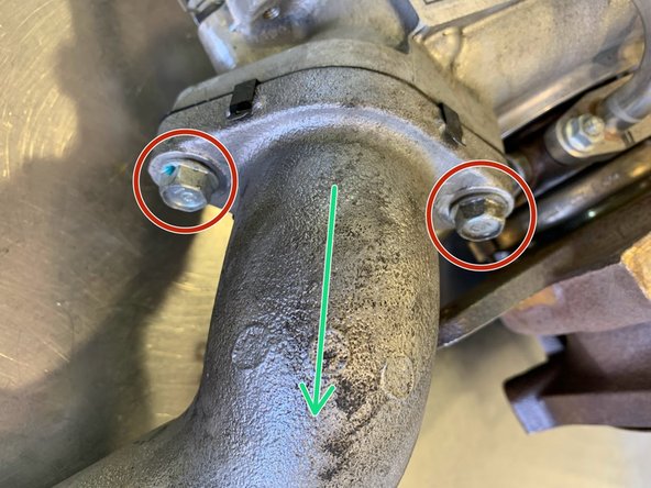
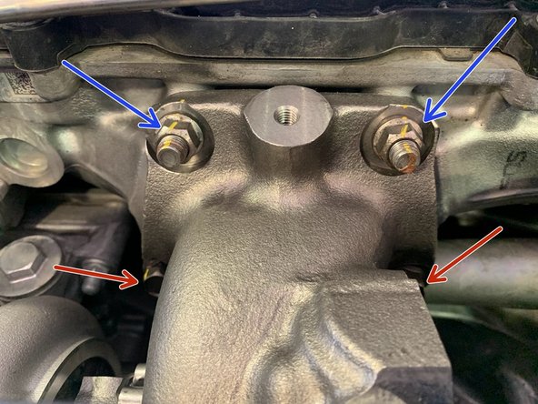
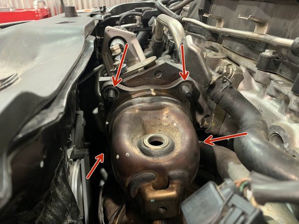
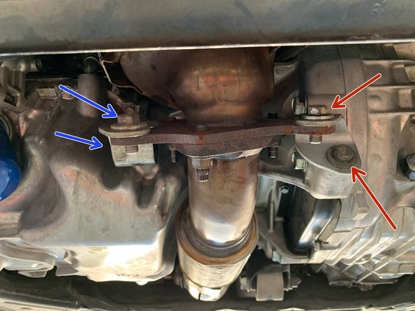
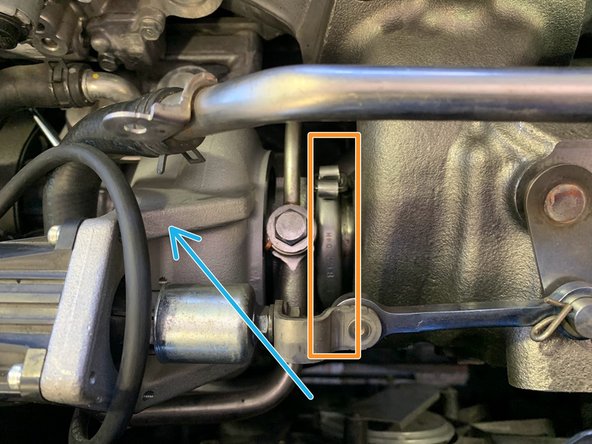
There are 2 nuts and 2 bolts that mount the Downpipe to the Turbo. Soak them with Penetrating fluid prior to attempting removal
-
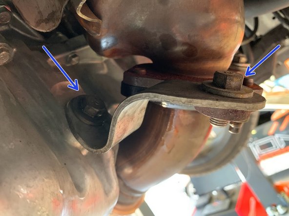
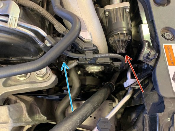
Break lose the (2) 14mm bolts (blue arrows) and the (2) 14mm nuts (red arrows)
-
Using a 14mm socket, remove the 2 nuts (red arrows)
-
Using a 14mm socket remove the 2 bolts (blue arrows) as shown
-
Remove the Downpipe from underneath the car
-
-
-
Undo the worm gear clamp with 10mm socket or screwdriver
-
Free the boost tube from compressor cover outlet
-
-
-
Undo the clamp from the hose as shown
-
Free the hose off the bung and set aside
-
-
-
Undo 14mm bolts holding support bracket in place
-
Remove the bracket and set it aside
-
-
-
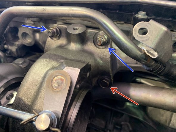
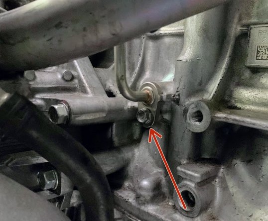
Remove the10mm bolt holding the hard oil feed line as shown
-
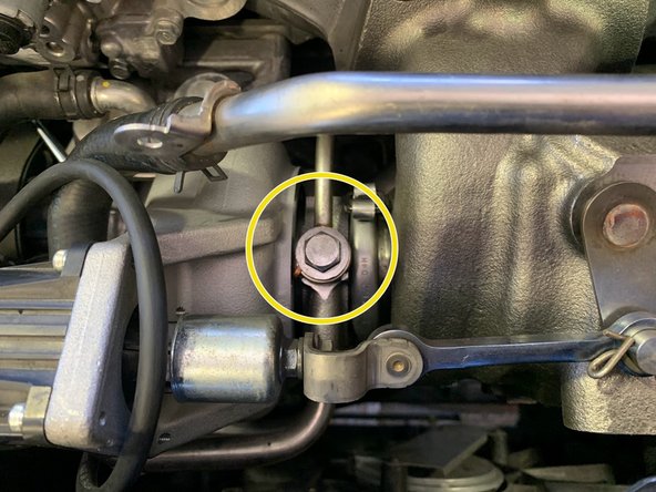
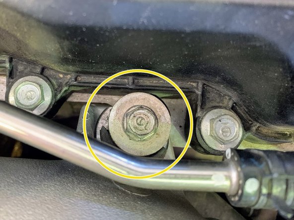
On the top, remove the 14mm bolt holding the hard oil feed line as shown
-
Remove the oil feed line and set aside
-
-
-
Undo other end of the Oil Control Solenoid pigtail harness as shown
-
-
-
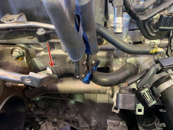
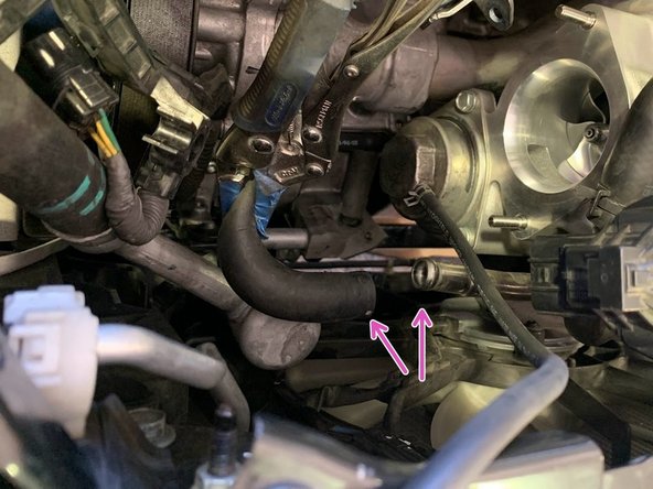
Remove the upper 10mm bolt holding the hardline next to the oil control solenoid pigtail electrical wiring clip unplugged in the previous step
-
Remove the lower 10mm bolt holding the hardline
-
Using Needle nose pliers, undo the clamp on the silicone section sitting just above the oil control solenoid electrical pigtail from the previous step. Free the hose from the hard line
-
-
-
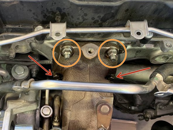
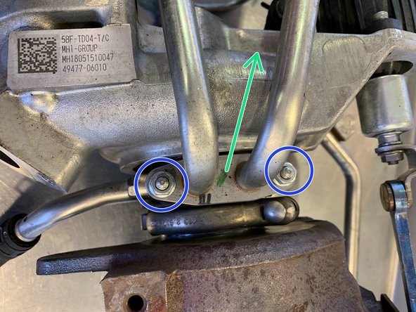
There are two 14mm bolts and two 14mm nuts holding the Turbo to the Cylinder Head
-
Undo the (2) 14mm bolts on the turbo housing
-
Remove the (2) 14mm nuts as shown
-
Its advised to lean the turbo assembly as shown to facilitate the next steps
-
-
-
A small amount of water and coolant will spill out. Prepare the area with paper towels
-
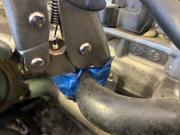
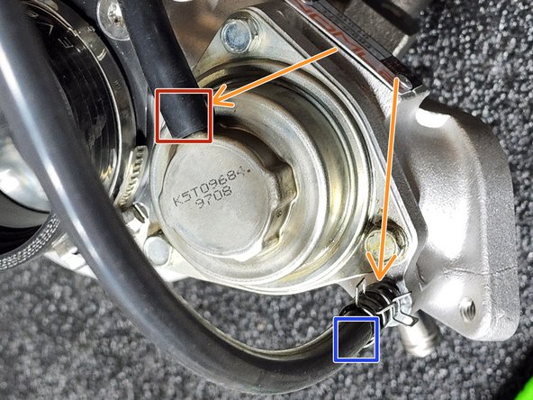
Undo the clamp holding the upper hose to the hard line
-
Using vice grip pliers with tape on the teeth to protect the hose, clamp (top, right next to turbo) hose to minimize water spillage
-
Proceed to the next step to free the lower coolant line before the upper. This will minimize coolant loss
-
-
-
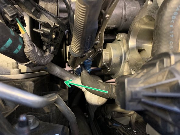
A small amount of water and coolant will spill out. Prepare the area with paper towels
-
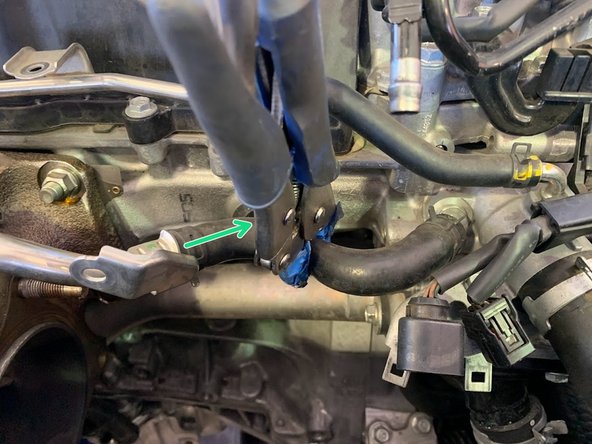
Using needle nose pliers, move the clamp up the silicone hose as shown
-
Using a second pair of vice grip pliers with tape on the teeth, clamp (top, right next to turbo) hose to minimize water spillage
-
Free the hose off of turbo assembly
-
-
-
Pull upper coolant hose off of hard line
-
-
-
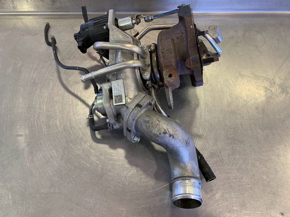
Remove the turbo assembly from the car and place on a workbench
-
-
-
Remove the (2)12mm bolts for the compressor cover outlet pipe
-
Remove the compressor cover outlet pipe and set aside
-
-
-
Remove the (2) 10mm nuts for the hard water lines and set them aside
-
Remove the hard water lines and set aside
-
For reinstall, a new OEM gasket may be needed (not included). Set aside existing gasket if you decide to reuse it
-
If you decide you need a new gasket, OEM part number: (19524-RPY-G01)
-
-
-
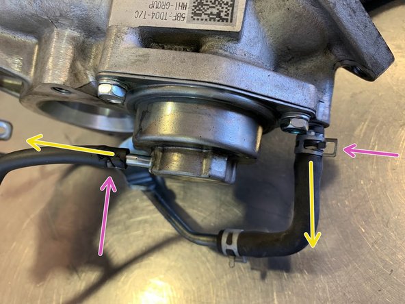
Loosen the clamps holding the vacuum hoses to turbo housing
-
Free the vacuum hoses from the nipple
-
-
-
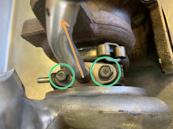
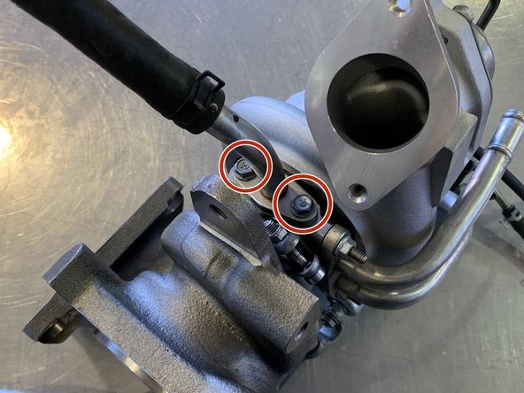
Remove the (2) 10mm bolts for the oil return hard pipe
-
Remove the oil return hard pipe and set aside
-
-
-
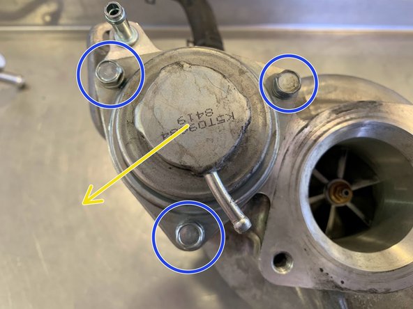
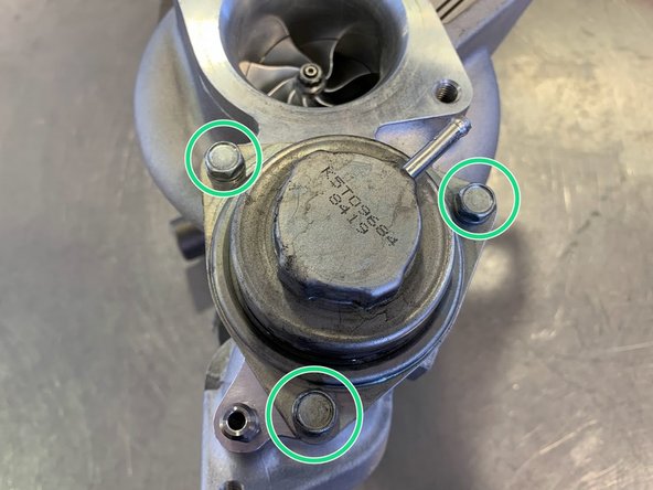
Remove the (3) 10mm bolts for the bypass valve
-
Set the Bypass Valve aside
-
-
-
A worn out or faulty bypass valve (BPV) can cause boost control issues and lead to premature turbocharger wear
-
Inspect diaphragm for any damage or cracks
-
You can apply vacuum to the nipple (with lips) and verify the BPV moves in as intended
-
Code P2261 indicates a problem with boost control. This can be due to a faulty BPV. This can over spin the turbo and damage it
-
-
-
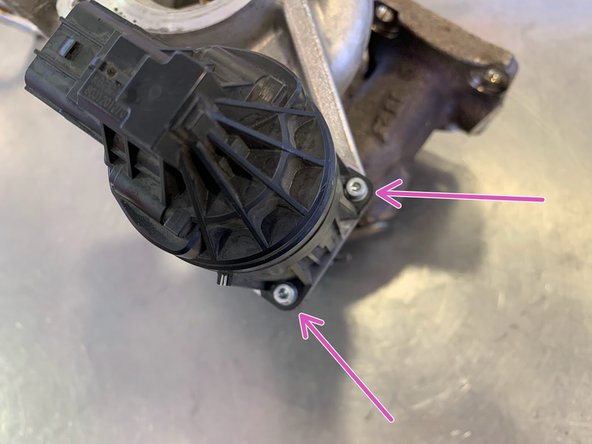
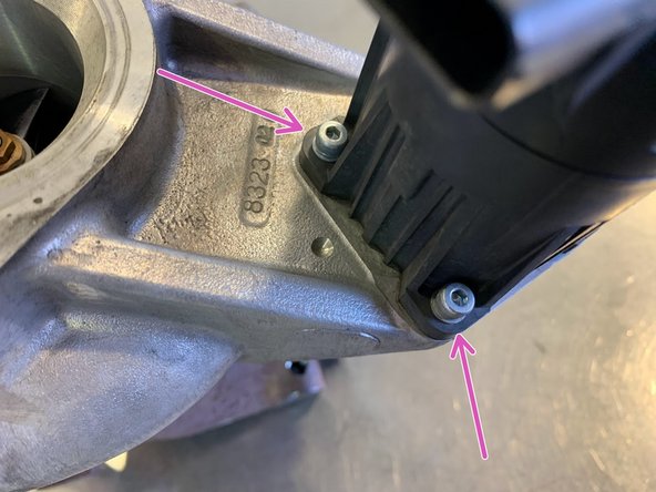
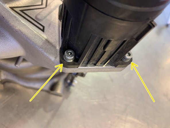
Using a 3mm Allen Key socket, remove the (4) 3mm Allen head bolts for the Electronic Wastegate
-
WARNING: Do not touch this interface or Wastegate calibration could be knocked out of calibration requiring expensive dealer service to recalibrate
-
The next step will describe how to disconnect the wastegate actuator from the turbine housing
-
-
-
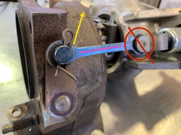
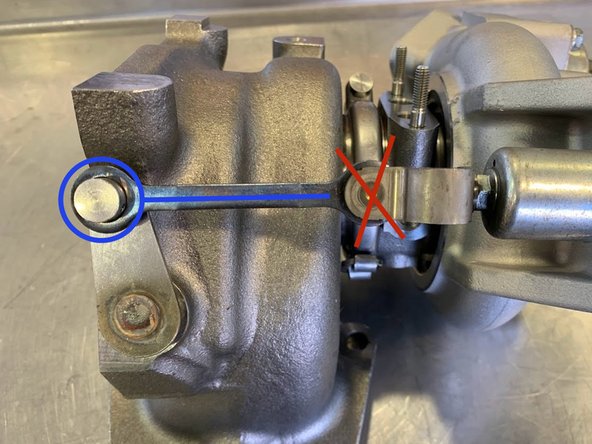
Using a pair of pliers, remove the retainer clip for the Electronic Wastegate
-
New line.
-
No not mess with this interface
-
Set the OE turbo aside
-
-
-
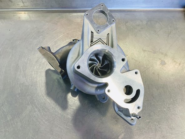
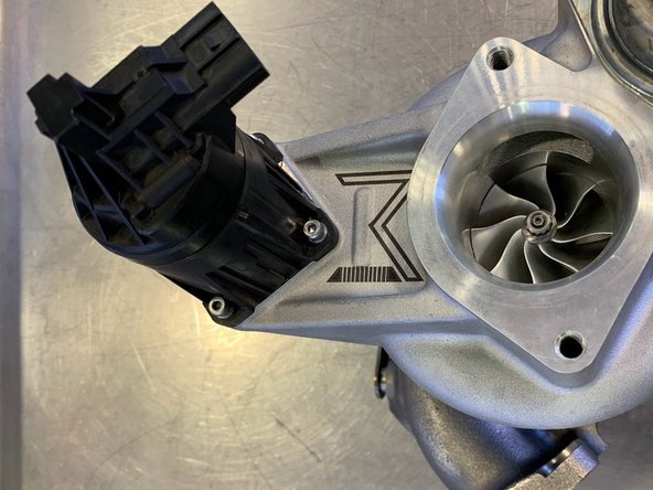
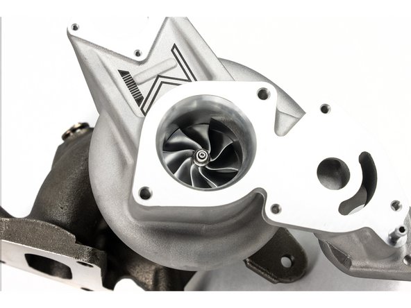
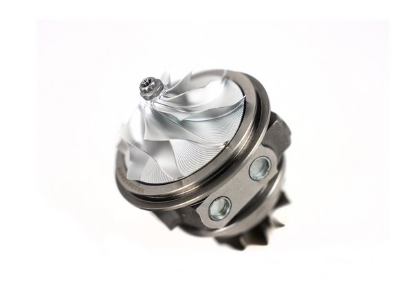
Set your new 27WON turbo on your workbench
-
-
-
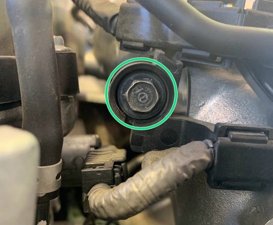
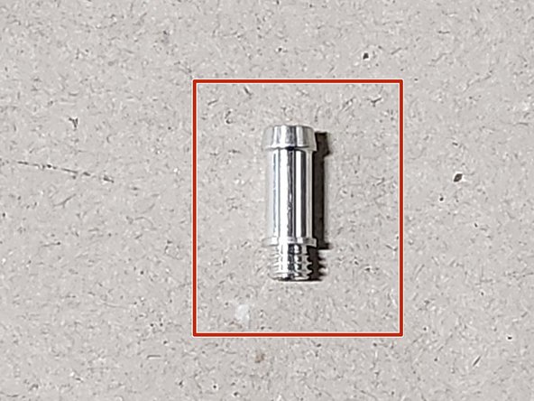
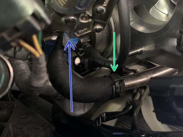
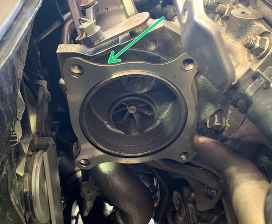
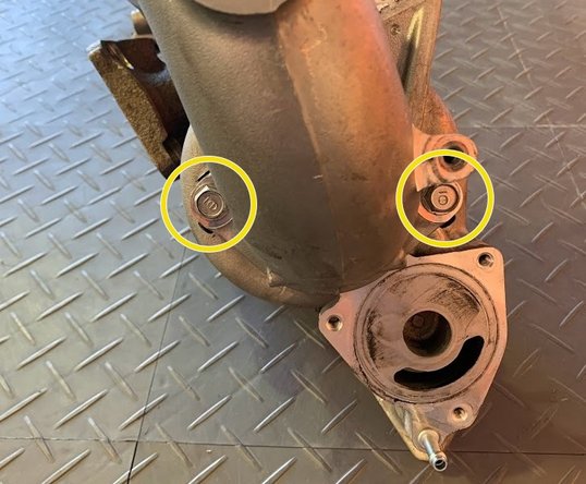
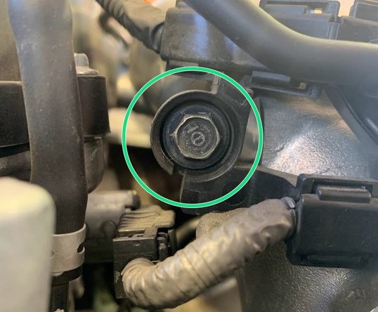
Locate the small silver vacuum barb in your hardware packet
-
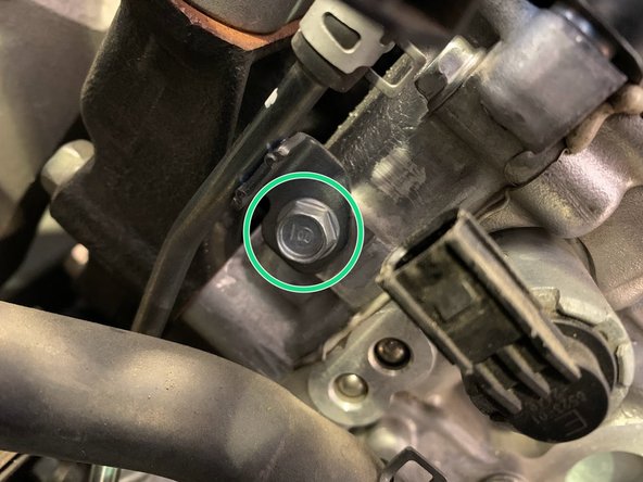
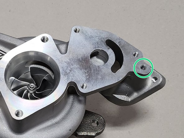
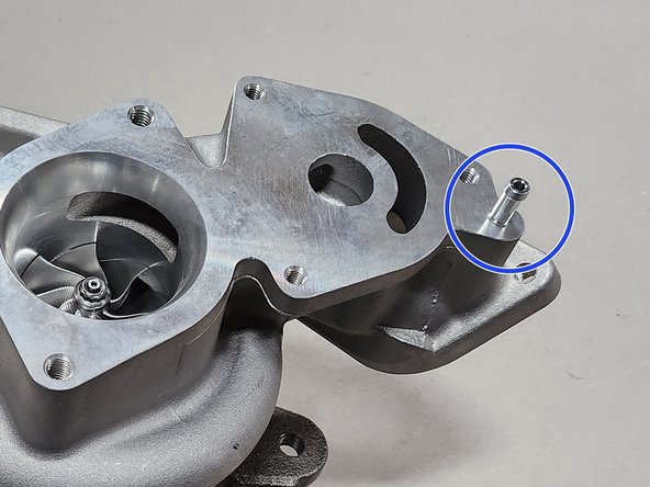
Thread by hand the barb into the area circled in green
-
Thread until flush with compressor cover
-
-
-
Position the Bypass valve as shown
-
Reinstall the OE (3) 10mm bolts. Torque to 9 ft-lb
-
-
-
Position the Electronic Wastegate as shown
-
Reinstall the (4) OE 3mm Allen head bolts
-
-
-
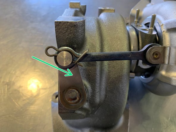
Re-hook the Electronic Wastegate Flapper Arm
-
Do not mess with this interface
-
Re-insert the retainer clip for the Electronic Wastegate Tail as shown
-
-
-
Position the gasket for the Hard Water Lines as shown
-
Re-install the Hard Water Lines with the OE (2) 10mm nuts. Torque to 9 ft-lb
-
-
-
Position the provided gasket for the Oil Return as shown
-
Reinstall the Oil Return Hard Pipe using the (2) OEM 10mm bolts as shown. Torque to 12 lb-ft
-
-
-
Install the provided silicone vacuum hoses onto the turbo
-
The shorter 5mm hose will go over your bypass nipple
-
The longer 4mm hose will go over the nipple on your compressor cover
-
Reinstall the retaining clamps where indicated
-
-
-
Position the Compressor Cover Outlet Pipe as shown
-
Reinstall the (2) OE 12mm bolts and secure the pipe. Torque to 33 lb-ft
-
-
-
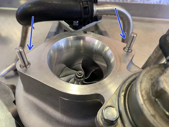
If your turbo did not come with two M8 studs and two M6 nuts for the turbo inlet pipe then skip this step. You'll reuse the OE bolts
-
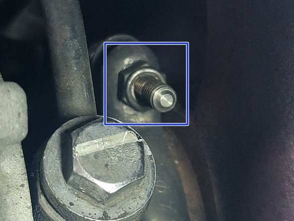
Thread the provided screws for the inlet face on to the turbo as shown
-
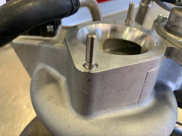
Ensure that the smaller thread section of the screws is exposed completely
-
DO NOT thread all the way. Leave the thread change section flush with inlet face as shown
-
-
-
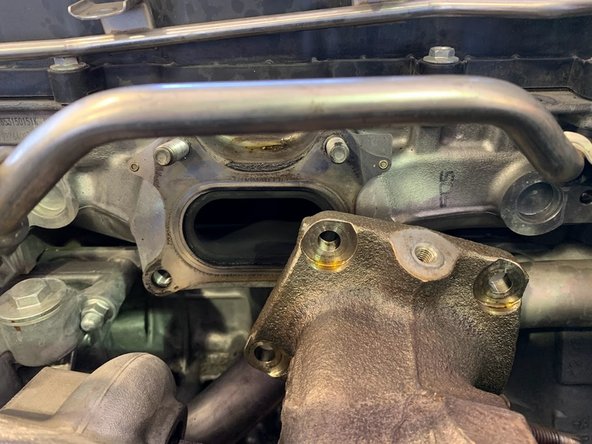
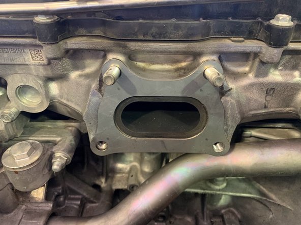
Install the provided turbo manifold gasket as shown
-
-
-
Insert the Turbo Assembly into the car as shown to facilitate the next steps
-
DO NOT bolt the assembly to the head. Allow the assembly to be loose in order to connect the various lines
-
-
-
Note: This is on the left (passenger side for USA) of the turbo
-
Reconnect the coolant hose
-
Reinstall the hose clamp as shown
-
Do not remove the vice grip pliers from the coolant hose until after next step to avoid spillage
-
-
-
Reconnect the coolant hose to the hard line
-
Reinstall the clamp as shown
-
Remove the vice grip pliers from both this upper hose and the lower hose from the previous step
-
-
-
Note: This step follows the same hardline/ silicone hose bundle. Moving from the lower point of the bundle to the connection to the hardline
-
Reinstall the 10mm bolt to the upper hardline mounting bracket. Torque to 9.8 ft-lb
-
Reinstall the 10mm bolt to the lower hardline mounting bracket. Torque to 9.8 ft-lb
-
Connect the silicone ends to the hardlines and reinstall the hose clamps were indicated
-
-
-
Align the holes of the turbine housing to the upper studs of the cylinder head
-
It is highly recommended to use anti-seize on these nuts and bolts
-
Reinstall the (2) OE 14mm bolts in the bottom holes as shown. Torque to 44 ft-lb
-
Reinstall the (2) OE 14mm nuts on the studs. Torque to 44 ft-lb
-
-
-
Route the oil feed line and using the provided 14mm Banjo bolt, reinstall as shown. Torque to 21 ft-lb
-
Reconnect the bottom side of the oil feed line using the OE 10mm bolt. Torque to 9 ft-lb
-
-
-
Reinstall Oil Return Hose back on to the bung
-
Secure the clamp as shown
-
-
-
Position the Turbo Support Bracket as shown
-
Reinstall the (2) 14mm bolts. Torque to 30 ft-lb
-
-
-
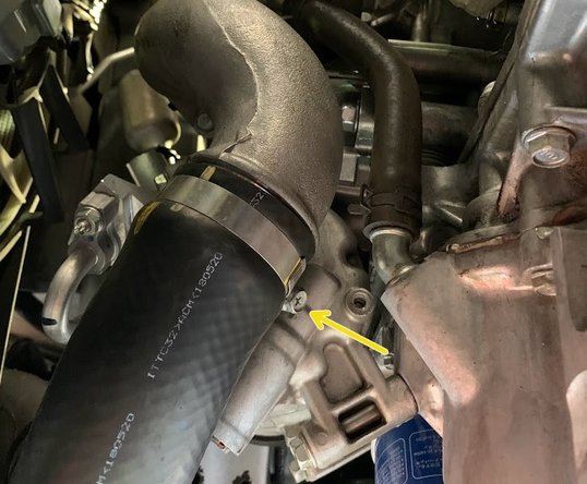
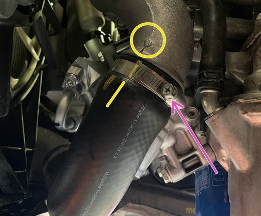
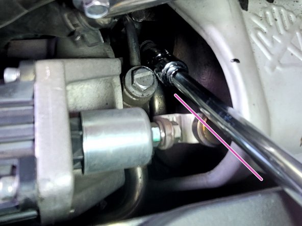
Reconnect the boost tube as shown
-
Make sure to align the yellow line with the arrow on the boost tube
-
Secure the worm clamp on the boost tube using either a screwdriver or a 10mm socket
-
-
-
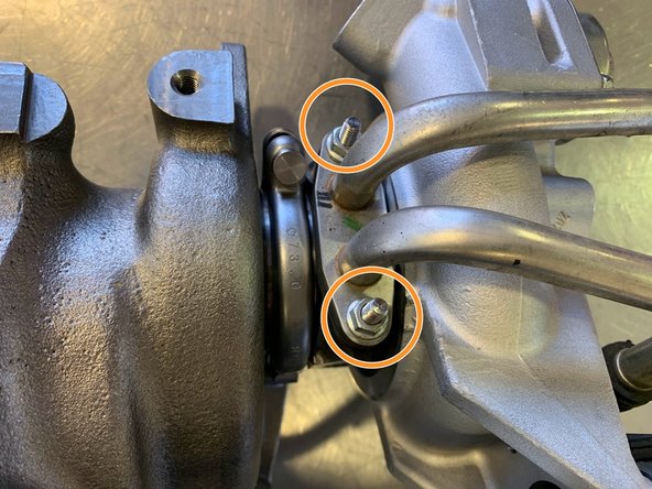
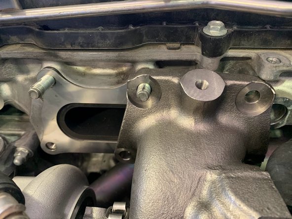
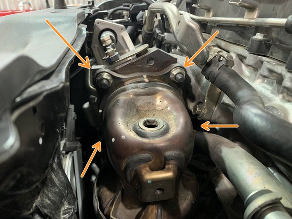
Thread the (4) provided studs into the marked locations
-
Shown with nuts installed, don't install nuts yet
-
-
-
Place provided gasket as shown
-
Shown without studs installed in previous step
-
Reinstall the downpipe onto the turbo over provided studs
-
Thread the (4) provided nuts onto the studs with anti-seize. Torque to 40 ft-lb
-
OEM downpipe shown, aftermarket downpipes may vary
-
-
-
Reconnect the lower oxygen sensor electrical pigtail as shown
-
-
-
Align the downpipe with the front pipe and reinstall the (3) OE 14mm nuts. Torque to 30-40 ft-lb
-
Reinstall the exhaust hanger for the front pipe
-
-
-
Align the left side bracket and reinstall the (2) OE 14mm bolts with anti-seize. Torque to 30-40 ft-lbs
-
Align the right side bracket and reinstall the (2) OE 14mm bolts with anti-seize. Torque to 30-40 ft-lbs
-
-
-
Install the (2) 12mm bolts from the upper part of the heat shield
-
It is very difficult to install the lowest bolt from the heat shield from above (as shown off the car). We advise to install this bolt from underneath
-
Install the lower 12mm bolt from the heat shield
-
-
-
To demonstrate the location of the mounting screws, the turbo inlet pipe is shown off the car
-
Use the provided (2) 10mm nuts to secure turbo inlet pipe to turbo
-
For Eventuri Turbo Inlet Pipe users: Use the Eventuri provided hardware. Slight modification to your Eventuri coupler may be necessary
-
-
-
Reinstall the (2) OE 10mm bolts to mount the top hard line to the intake pipe
-
Reinstall the (2) OE 10mm bolts to mount the bottom hard line to the intake pipe
-
Reinstall the OE 10mm bolt to mount the intake pipe as shown
-
-
-
There are 2 bolts holding this bracket. The lower one is well hidden (purple arrow)
-
Using the OE 10mm bolt reinstall the upper part of the vacuum line bracket as shown
-
Using the OE 10mm bolt reinstall the lower part of the vacuum line bracket as shown
-
-
-
Plug elect pigtail of electronic wastegate
-
Follow the wire up and reconnect the other end of the electrical harness as shown
-
-
-
Reinstall the upper oxygen sensor using the 22mm oxygen socket. Torque to 30 ft-lbs
-
Reconnect wiring harness for upper oxygen sensor
-
-
-
Reinstall the intake tube as shown and secure the clamps with a 5.5mm socket
-
Secure the hard pipe with the provided 14-27mm hose clamp as shown
-
OE Clamp is shown and cannot be reused
-
Use needle nose pliers to clamp the OEM spring clamps for the EVAP silicon Boost feed and EVAP dump hoses
-
-
-
Use a 10mm socket and install the 5 bolts to hold the engine cover
-
-
-
Lift the under tray into position
-
Reinstall the five 10mm bolts with a 10mm socket & torque wrench. Torque to 6-8 lb-ft
-
Reinstall the two 5mm socket flange bolts with the 5mm Allen key & torque wrench. Torque to 6-8 lb-ft
-
Reinstall the 19 push clips at the bottom of the undertray and the sides
-
For clarity on the push clips on the sides of the under tray (labeled with the arrows) please see the next step
-
-
-
The images in this step show the push clips on the side of the under tray. These are labeled with the arrows in the previous step
-
-
-
Please be aware that some coolant has been removed from your car. It is HIGHLY ADIVISED to refill the coolant reservoir with new coolant
-
Leave the radiator cap off the coolant tank for 5 minutes while the car warms to bleed air out of the system. Fill tank with coolant as needed to reach correct level on the fill line
-
Reinstall cap once done bleeding air out
-
-
-
Check the engine coolant level in the reservoir for the next few days as the air in the cooling system works itself out. Refill as needed
-
Some smell and faint smoke can be present on first start-up. This is normal and will not happen after the 2nd or 3rd heat cycle.
-
To get the best performance from your Kuro Turbo, we highly recommend a custom tune
-
A custom tune for your specific vehicle with your specific modifications will provide the best performance for your Civic and the location you live in
-
Please see the next step for expectations for driving a performance turbo equipped vehicle
-
-
-
Check T-bolt clamp after around 1,000 miles to make sure it's not loose
-
If it's loose the clamp may rotate
-
If it's loose the compressor cover may wiggle or rotate
-
If clamp is found to be loose then rotate it around until you can access the nut
-
This can be done without removing the heat shield or taking the turbo out of the car
-
Tighten the nut to 62 lbs-in (7 N-m) with a torque wrench, extension, and 10mm socket
-
-
-
A vehicle equipped with a larger performance turbocharger may require a change in the way it is driven. A properly tuned vehicle with a larger turbocharger definitely will
-
A properly tuned vehicle with a larger turbocharger will experience peak torque later in the RPM range. This may make the vehicle feel more sluggish in the the lower RPM range, approximately sub 3000rpm. However, peak power will also move higher in the RPM range and carry to redline
-
We recommend shifting at a higher RPM (~300rpm higher) to combat this feeling
-
A larger performance turbocharger will also create more pronounced turbo induction noises, your gas mileage may drop significantly for the first few tanks from you constantly wanting to hear the turbo spool
-
-
-
This completes the installation of your 27WON Performance FK8 Kuro Turbo
-
We hope you were impressed with your 27WON experience and love your new Kuro Turbo for years to come. Email us at sales@27won.com or call us at 571-271-0271 with any questions or concerns
-
Please Leave a review here: https://store.27won.com/2017-2021-civic-...
-
Stay Connected with the latest developments with the 27WON Monthly Newsletter: https://store.27won.com/27won-newsletter...
-
See the latest Products and Tech Videos from 27WON with a quick Subscribe: https://www.youtube.com/channel/UCF7uI0N...
-
Share your experience using #27WON on Instagram and Facebook
-