Introduction
In this installation guide we have provided step by step instructions to setup, remove the OEM boost tubes, and install the 27WON Performance Boost Tubes.
Advisory:
- Working under the vehicle requires a safe and sturdy location for the vehicle to sit on jackstands.
- The engine bay will be hot after recent vehicle operation. Allow the vehicle to cool or use a fan to cool the engine bay before working on the vehicle.
Tools
-
-
First and foremost; THANK YOU for becoming a part of the 27WON Family. We hope to REDEFINE your experience of the aftermarket with the highest level Parts, Customer Service, Packaging, & Support
-
The 27WON Boost Tubes are designed as an OEM fitment replacement and closely match overall size and routing, however fitment with non-27WON aftermarket intake systems is not guaranteed.
-
-
-
As of June 2021 this kit comes with Throttle Body Silicone. Installation instructions for that part are separate from these instructions and can be performed before or after the boost tubes.
-
To install the 27WON FK8 throttle body silicone please review these install instructions before proceeding: FK8-6-143 Throttle Body Silicone
-
-
-
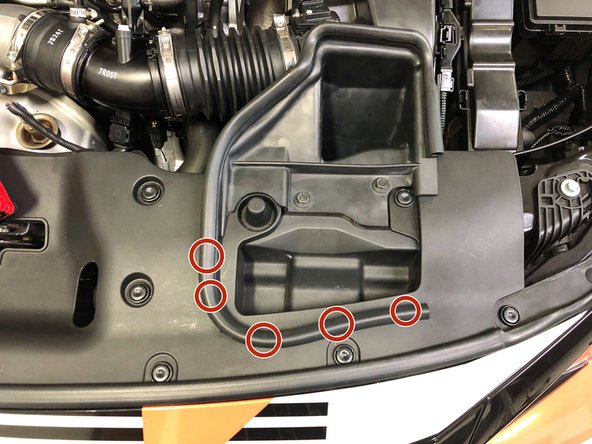
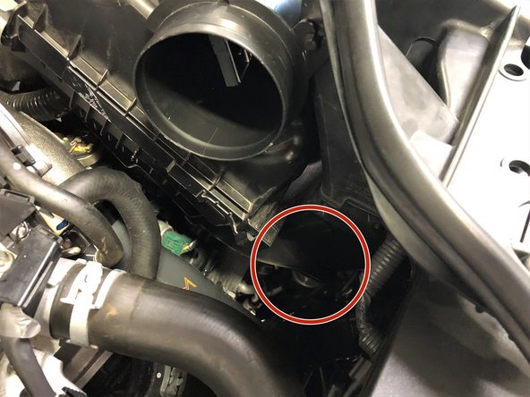
Begin by freeing the OEM weatherstripping from the upper radiator panel
-
There are five push clips, roughly marked with red circles in the image, that are removed by pulling upwards on the weatherstripping
-
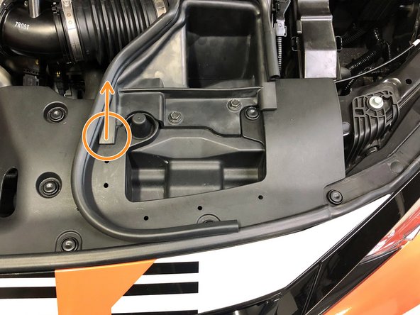
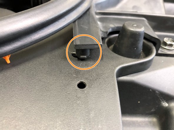
Free the large rubber tab (orange circle) from the corner of the OEM intake duct by pulling upwards
-
-
-
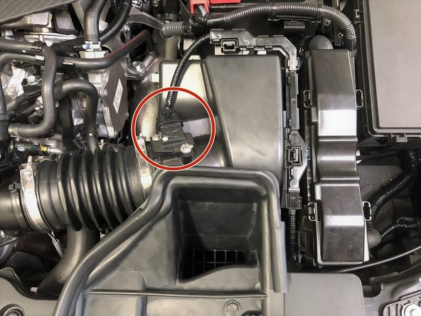
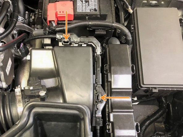
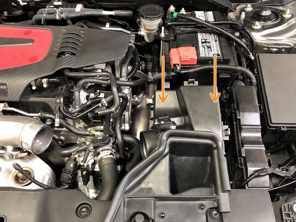
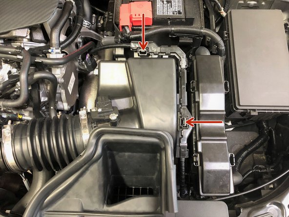
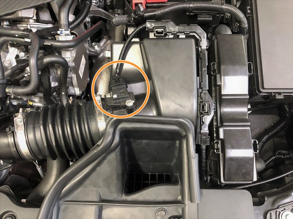
Unplug the MAF sensor by pushing down on the tab (red circle) on top of the wiring connector
-
Unclip the MAF sensor wiring from the OEM airbox by sqeezing the two tabs shown by orange arrows then pull up
-
Set the MAF sensor wiring out of the way
-
-
-
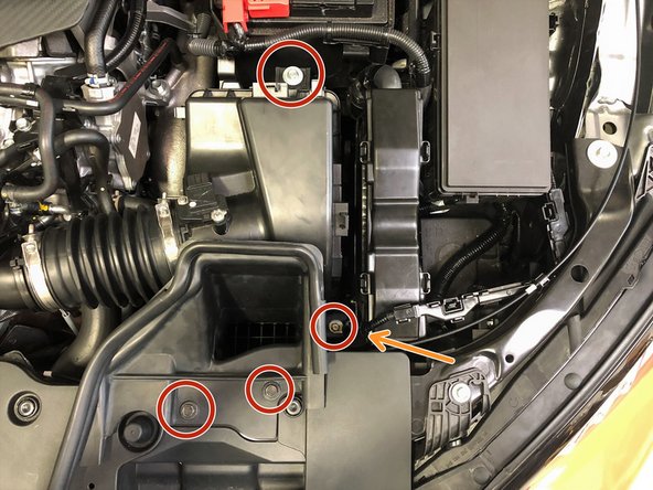
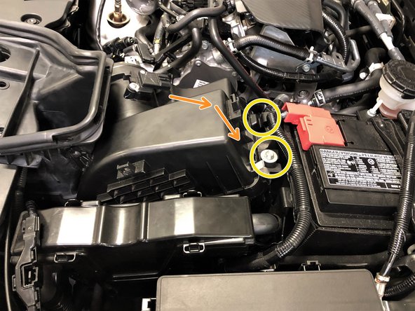
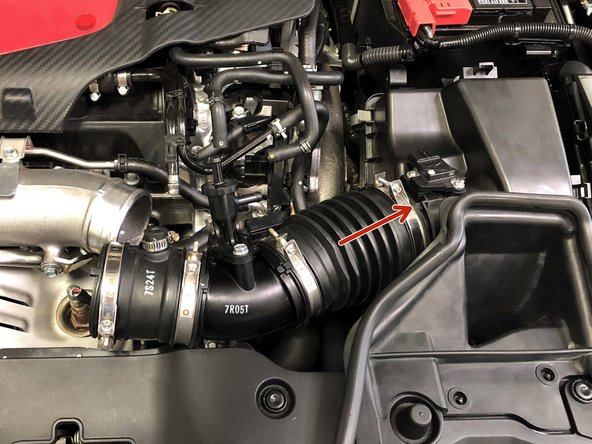
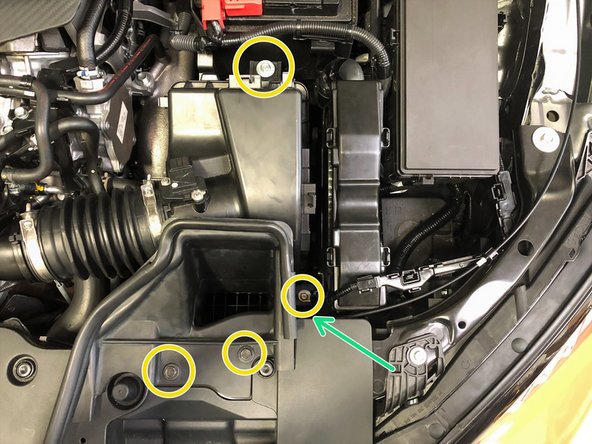
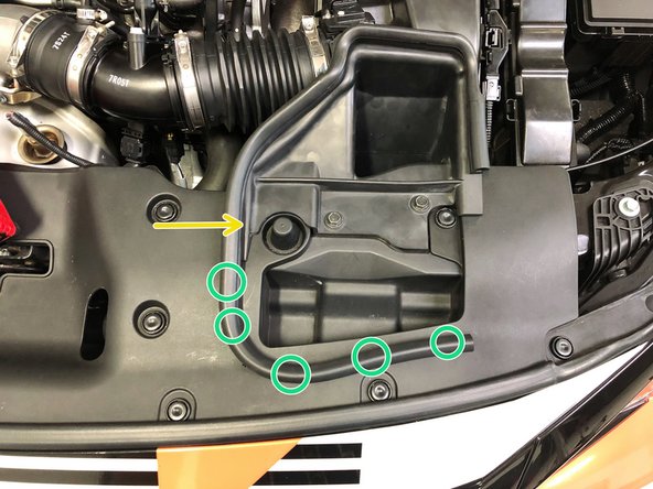
Remove the four 10mm bolts that attach the OEM intake to the vehicle using a 10mm socket and ratchet
-
TIP: A long extension will need to be used to loosen the bolt with the orange arrow. This bolt will stay captive in the OEM intake and does not need to be fully removed
-
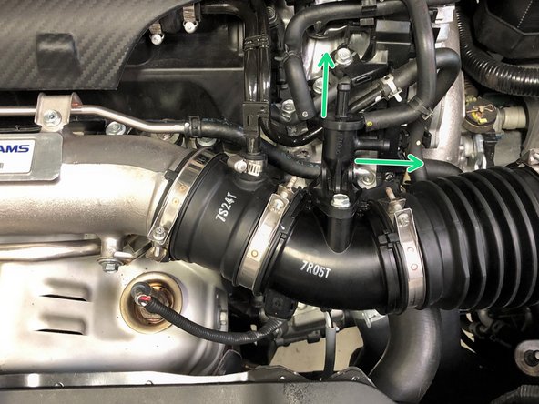
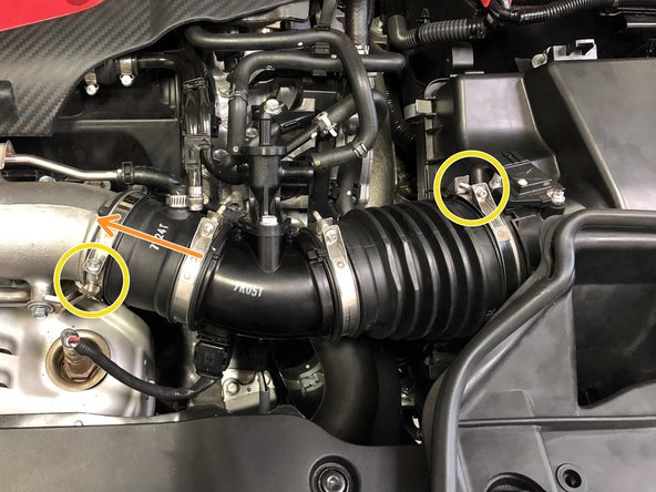
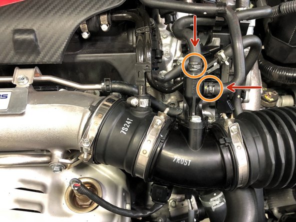
Use needle nose pliers to loosen the OEM spring clamps and slide them up the hoses of the EVAP solenoid
-
Pull the hoses off the EVAP solenoid
-
-
-
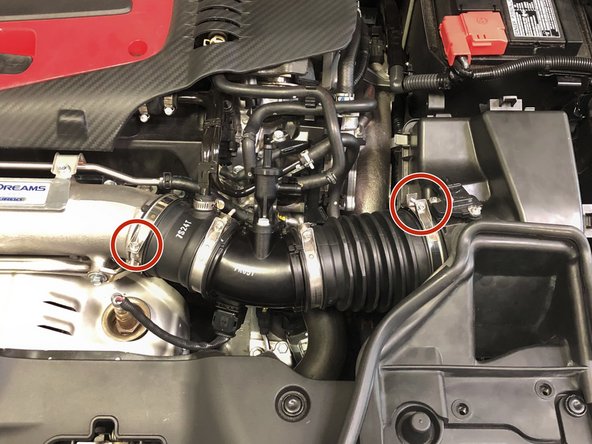
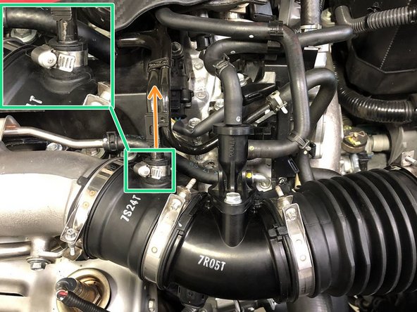
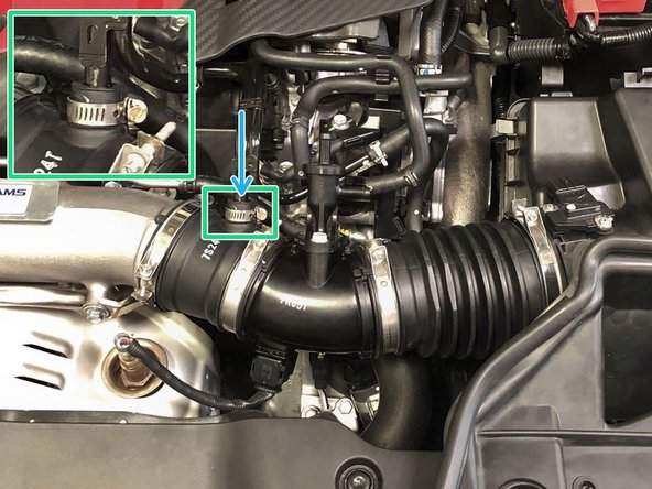
Using the 5.5mm socket and ratchet, loosen the two OEM clamps securing the intake tube
-
Remove the valve cover breather pipe from the intake tube
-
This breather pipe is secured with a permanent OEM clamp. This clamp cannot be removed easily so the pipe will need to be pulled free without removing the clamp. This can be difficult the first time. This permanent clamp will be replaced with the provided regular hose clamp during re-installation
-
Remove the OEM intake tube from the vehicle
-
-
-
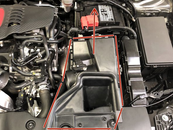
Pull the OEM airbox upwards to free it from the lower rubber grommet. It should pop free with a little force
-
Now move to the driver side of the engine for the next step
-
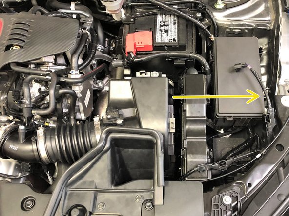
Pivot the OEM airbox forward to allow clearance for the rear mounts of the airbox past the battery cable
-
The battery cables will need to flex slightly to clear the rear airbox mounts
-
Remove the airbox from the vehicle
-
-
-
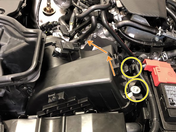
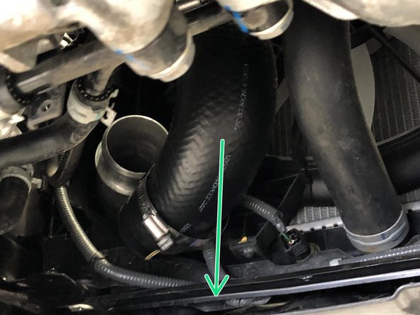
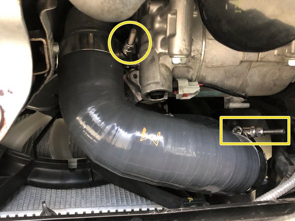
Locate the cold side boost tube
-
Using a 10mm socket and ratchet, loosen the clamp where the OEM boost tube connects to the OEM cold pipe
-
Slide this clamp down the OEM boost tube
-
Pull the OEM boost tube free from the OEM cold pipe
-
-
-
Raise the vehicle and support with jackstands in the OE recommended locations
-
Locate the engine undertray to gain access to the OEM hot side boost tube and lower section of the OEM cold side boost tube
-
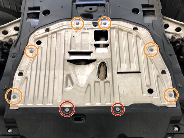
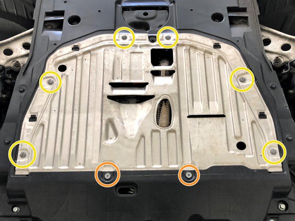
Remove the two Phillips head screws using a Phillips screwdriver
-
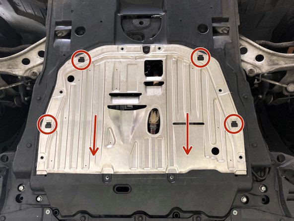
Remove the six quarter turn screws using a large Flathead screwdriver
-
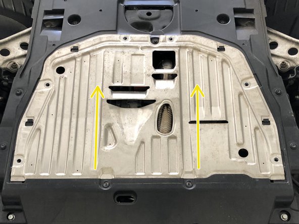
Slide the metal section rearward and remove it from the vehicle
-
The metal section of the undertray can be sharp. Use caution when handling it
-
-
-
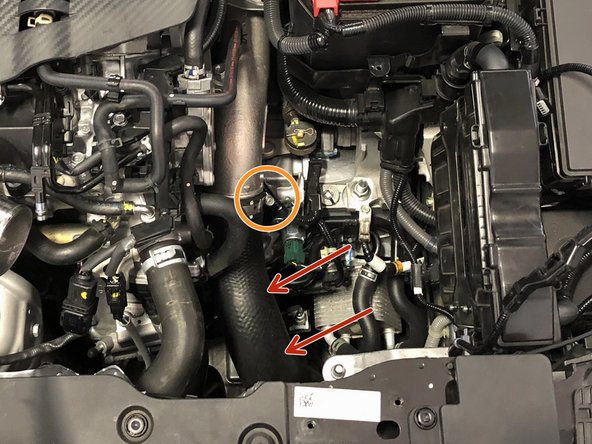
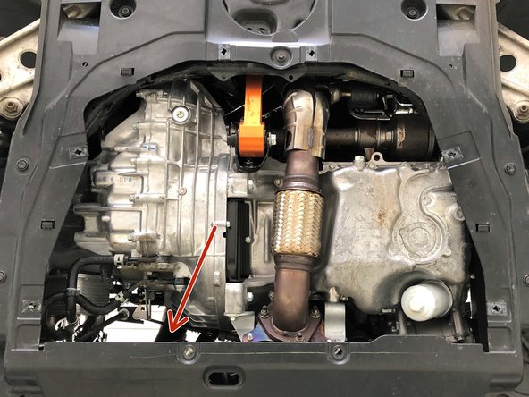
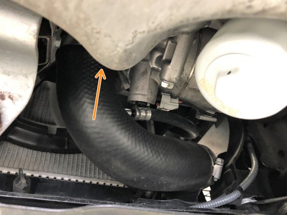
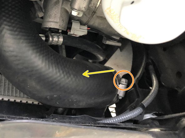
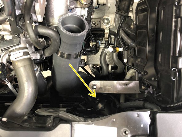
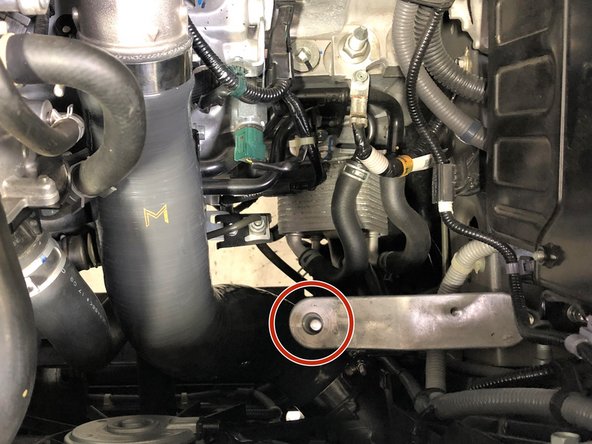
Locate the lower portion of the OEM cold side boost tube. It's in the general area of the red arrow
-
Loosen the clamp that connects the OEM cold side boost tube to the intercooler using a 10mm socket and ratchet
-
Slide the clamp up the tube and out of the way
-
Pull the OEM boost tube free from the intercooler and remove it from the vehicle
-
-
-
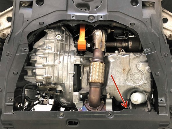
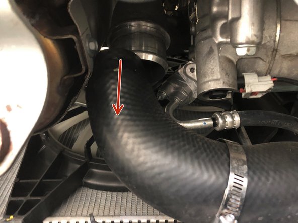
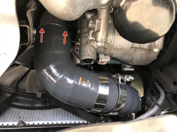
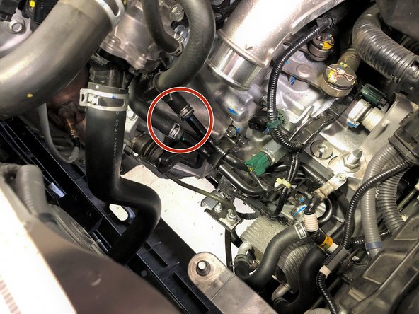
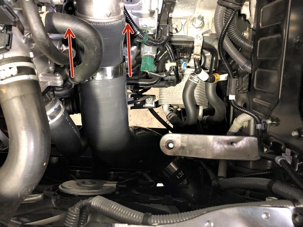
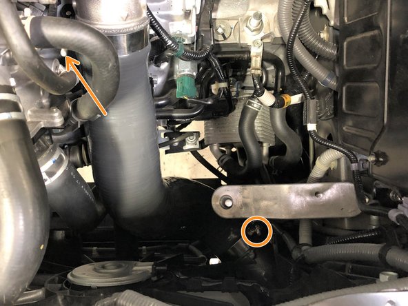
Locate the OEM hot side boost tube. It's in the general area of the red arrow
-
Loosen the clamp that connects the OEM hot side boost tube to the turbocharger using a 10mm socket and ratchet
-
Slide the clamp toward the center of the OEM hot side boost tube and out of the way
-
-
-
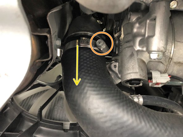
Pull the OEM boost tube free from the turbocharger
-
Loosen the clamp that attaches the OEM hot side boost tube to the intercooler using a 10mm socket and ratchet
-
Slide this clamp toward the center of the OEM boost tube and out of the way
-
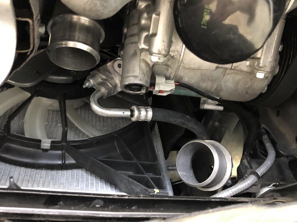
Pull the OEM boost tube free from the intercooler and remove it from the vehicle
-
-
-
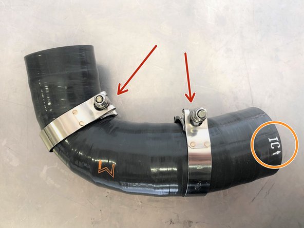
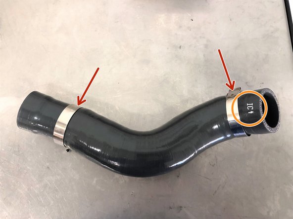
Locate the 27WON hot side boost tube
-
Install the two supplied 60-68mm clamps near the center of the boost tube as shown
-
Position the boost tube in the OEM location
-
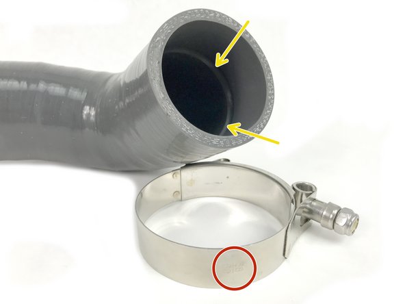
The end with "IC" and the arrow attaches to the intercooler
-
Push the 27WON boost tube onto the intercooler
-
The inner groove on the 27WON boost tubes will "pop" into position when the intercooler pipe is fully seated in the silicone
-
-
-
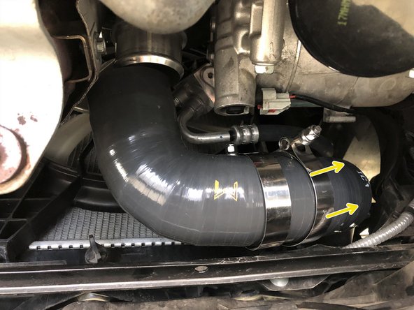
Slide the other end of the 27WON hot side boost tube over the outlet of the turbocharger
-
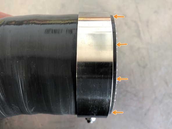
Image 2 on this page shows what we mean by "correctly positioning" the clamps. There should be a small gap between the clamp and the end of the silicone (2-4mm). This gap should be even all the way around the silicone. Use this image as a reference when tightening all supplied clamps
-
Correctly position the two 60-68mm clamps and tighten with a 10mm socket and ratchet until the silicone starts to bulge slightly at the edge of the clamp
-
The clamp orientations shown are the easiest to access/tighten
-
-
-
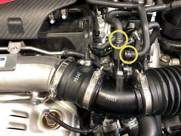
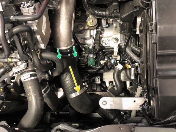
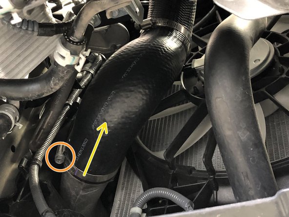
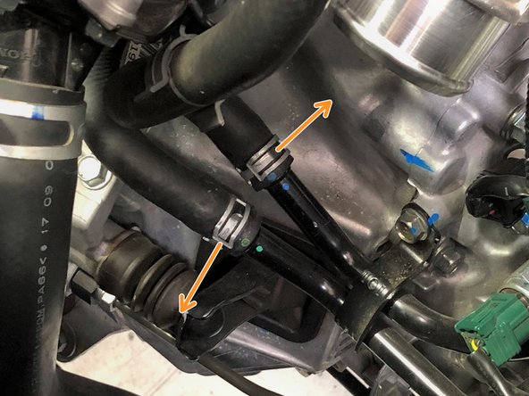
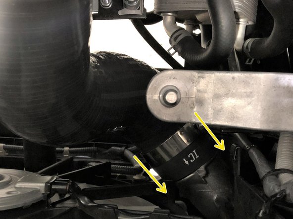
From above the vehicle locate the two spring clamps on the coolant lines that run below the cold side boost tube
-
To gain extra clearance for the larger 27WON boost tube, these clamps will need to be rotated out of the way
-
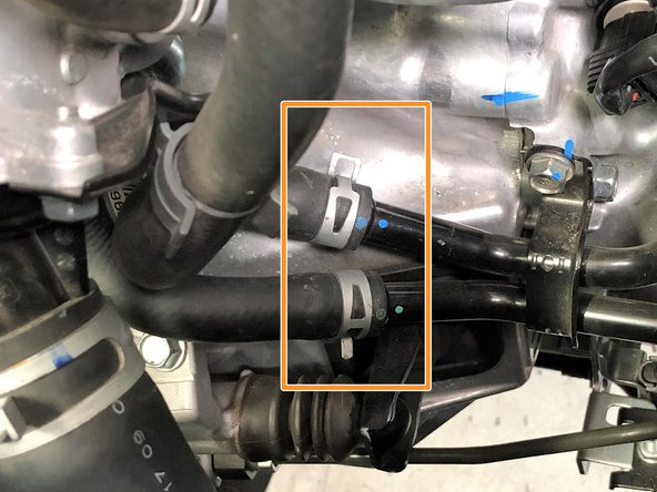
Use needle nose pliers to rotate the upper clamp towards the rear of the car, and the lower clamp towards the front of the car
-
Ensure the "tabs" of the spring are not facing outwards where they could rub on the boost tube
-
-
-
Locate the 27WON cold side boost tube
-
Install the two supplied 63-71mm clamps away from the ends of the silicone as shown
-
Position the boost tube in the OEM location
-
The end with "IC" and the arrow attaches to the intercooler
-
Push the 27WON boost tube onto the intercooler
-
The inner groove on the 27WON boost tubes will "pop" into position when the intercooler pipe is fully seated in the silicone
-
-
-
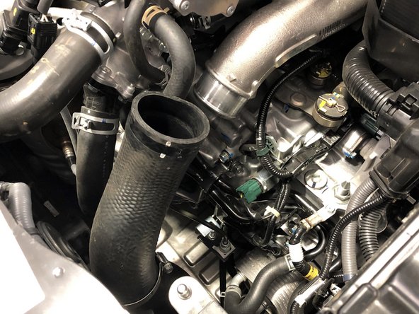
Slide the other end of the 27WON cold side boost tube over the cold pipe
-
You will likely need to flex the silicone to get it to slide over the cold pipe into position
-
Correctly position the two 63-71mm clamps and tighten with a 10mm socket and ratchet until the silicone starts to bulge slightly at the edge of the clamp
-
See step 13 for correct clamp positioning
-
The clamp orientations shown are easy to access and provide clearance to airboxes and intakes
-
-
-
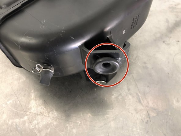
When reinstalling the airbox there is a rubber grommet on the bottom of the box that must fit on an aluminum peg in the engine bay
-
Insert the airbox into the engine bay in a similar manner that it was removed
-
The front will sit in an approximately correct location while the back pivots downward
-
Use care when maneuvering the rear brackets around the battery cables so as to not damage the cables
-
-
-
Once clear from the battery cables, reach your hand under the airbox to align the rubber grommet on the metal peg shown in the previous step (second image)
-
You can see edge of the metal peg if needed to help align the airbox
-
You will likely need to move the airbox around to get the peg and grommet aligned
-
Push downwards to seat the grommet on the peg
-
-
-
Reinstall the OEM intake tube by first sliding it on the airbox
-
Then slide the OEM intake tube onto the turbo inlet pipe
-
Tighten the clamps securing the intake tube using a 5.5mm socket and ratchet
-
Remove the OEM clamp and replace with the provided clamp as shown
-
Insert the valve cover breather tube back into the OEM intake tube
-
Tighten the clamp with a flathead screwdriver until the rubber begins to bulge slightly
-
-
-
Reinstall the two hoses onto the EVAP solenoid
-
Secure the hoses using needle nose pliers to move the spring clamps into position
-
Secure the OEM airbox using a 10mm socket, ratchet, and the bolts removed/loosened earlier. Tighten all bolt to 8-10 ft-lbs
-
The bolt with the green arrow will need a long extension to reach
-
-
-
Install the MAF sensor wiring back onto the airbox by pushing downwards until the two clips click into place
-
Reconnect the MAF sensor to the MAF wiring. Push the connector on until it clicks into place
-
Reinstall the rubber tab in the corner of the OEM air duct onto the upper radiator panel
-
Reinstall the weatherstripping onto the upper radiator panel. The five clips will click into place
-
-
-
Lift the metal section of the undertray into position
-
The front edge of the metal will fit over the top of the rear edge of the plastic section of the undertray
-
To secure, push the skidtray forwards onto the four tabs that will hold it in position
-
Reinstall the two Phillips head screws and tighten until tight using a Phillips screwdriver
-
Reinstall the six quarter-turn screws and tighten using a large Flathead screwdriver. This will "click" into position when tight
-
-
-
This completes the installation of your 27WON Performance Boost Tubes. If you still need to install your 27WON Performance FMIC, you can do that here:https://www.performanceinstalls.com/Guid...
-
We hope you were impressed with your 27WON experience and love your new Boost Tubes for years to come. Email us at sales@27won.com or call us at 571-271-0271 with any questions or concerns
-
Please Leave a review here: https://store.27won.com/civic-type-r-int...
-
Stay Connected with the latest developments with the 27WON Monthly Newsletter: https://store.27won.com/27won-newsletter...
-
See the latest Products and Tech Videos from 27WON with a quick Subscribe: https://www.youtube.com/channel/UCF7uI0N...
-
Share your experience using #27WON on Instagram and Facebook
-